Donations help to keep the site running:
Home
![]() Software
Software
![]() VHDL CPLD Course
VHDL CPLD Course
![]() Tut4 Multiplexers
Tut4 Multiplexers
Tutorial 4: Multiplexers in VHDL
Created on: 24 December 2012
A multiplexer allows digital signals from several sources to be routed onto a single bus or line. A 'select' input to the multiplexer allows the source of the signal to be chosen.
We look at two multiplexer examples in this tutorial, the first multiplexes two 4-bit input buses to a single 4-bit output bus, the second example multiplexes four single input lines to a single output line.
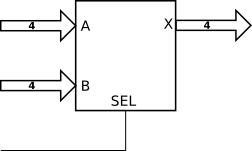
Four-Bit Wide 2 to 1 Multiplexer
The 2 to 1 multiplexer is shown below. A logic 1 on the SEL line will connect the 4-bit input bus A to the 4-bit output bus X. A logic 0 on the SEL line will connect input bus B to output bus X.
VHDL Code
The VHDL code for implementing the 4-bit 2 to 1 multiplexer is shown here.
library IEEE;
use IEEE.STD_LOGIC_1164.ALL;

entity mux_2to1_top is
    Port ( SEL : in  STD_LOGIC;
           A   : in  STD_LOGIC_VECTOR (3 downto 0);
           B   : in  STD_LOGIC_VECTOR (3 downto 0);
           X   : out STD_LOGIC_VECTOR (3 downto 0));
end mux_2to1_top;

architecture Behavioral of mux_2to1_top is
begin
    X <= A when (SEL = '1') else B;
end Behavioral;
The VHDL when and else keywords are used to implement the multiplexer.
The when-else construct is a conditional signal assignment construct that assigns the signal on the left of when (A in our example) to the output signal (X in our example) if the condition to the right of when is true (SEL = '1' – if SEL is equal to logic 1). If the condition is false, then the signal to the right of the else (B) will be assigned to the output signal instead (this will occur if the signal on SEL is a logic 0).
The result of this signal assignment is that a logic 1 on SEL will connect the 4-bit input bus A to the 4-bit output bus X. A logic 0 on SEL will connect the 4-bit input bus B to the output bus X.
Source Code
The source files for the 4-bit 2 to 1 multiplexer can be downloaded here. The UCF and JED files are configured for use on the home made CPLD board.
The VHD, UCF and JED files: mux_2to1_4bit.zip (6.1kB)
One-Bit Wide 4 to 1 Multiplexer
A four to one multiplexer that multiplexes single (1-bit) signals is shown below. The two SEL pins determine which of the four inputs will be connected to the output.
00 on SEL will connect A(0) to X, 01 on SEL will connect A(1) to X, etc.

VHDL Code
The VHDL code that implements the above multiplexer is shown here.
library IEEE;
use IEEE.STD_LOGIC_1164.ALL;

entity mux_4to1_top is
    Port ( SEL : in  STD_LOGIC_VECTOR (1 downto 0);     -- select input
           A   : in  STD_LOGIC_VECTOR (3 downto 0);     -- inputs
           X   : out STD_LOGIC);                        -- output
end mux_4to1_top;

architecture Behavioral of mux_4to1_top is
begin
with SEL select
    X <= A(0) when "00",
         A(1) when "01",
         A(2) when "10",
         A(3) when "11",
         '0'  when others;
end Behavioral;
In this code, the with, select and when VHDL keywords are used.
The line with SEL select sets up SEL as the signal that is evaluated by the when statements that follow. When the logic levels on SEL match one of the values to the right of one of the when statements, the signal to the left of that when statement will be assigned to the output signal (X).
The line containing 'others' is required by VHDL to take care of any logic combination that is not taken care of by the preceding statements. This allows for any states besides logic 0 and 1 levels, such as high impedance signals - Z.
Note that single signals are assigned logic values by using single quotes, e.g. '0'. A group of signals (vectors) are assigned values between double quotes, e.g. "01".
Alternate VHDL Code Using when-else
This code implements exactly the same multiplexer as the previous VHDL code, but uses the VHDL when-else construct. This is the same when-else as the first example (2 to 1 MUX), but this time multiple when-else constructs are used.
library IEEE;
use IEEE.STD_LOGIC_1164.ALL;

entity mux_4to1_top is
    Port ( SEL : in  STD_LOGIC_VECTOR (1 downto 0);     -- select input
           A   : in  STD_LOGIC_VECTOR (3 downto 0);     -- inputs
           X   : out STD_LOGIC);                        -- output
end mux_4to1_top;

architecture Behavioral of mux_4to1_top is
begin
    X <= A(0) when (SEL = "00") else
         A(1) when (SEL = "01") else
         A(2) when (SEL = "10") else
         A(3) when (SEL = "11") else A(0);
end Behavioral;
Source Code
The source files for the 1-bit 4 to 1 multiplexer can be downloaded here. The UCF and JED files are configured for use on the home made CPLD board.
The VHD, UCF and JED files: mux_4to1_1bit.zip (6.1kB)