Donations help to keep the site running:
Home
![]() Software
Software
![]() VHDL CPLD Course
VHDL CPLD Course
![]() Tut12_ring_counter
Tut12_ring_counter
Tutorial 12: Ring Counters in VHDL
Created on: 8 February 2012
A ring counter is simply a shift register that feeds the last bit of the shift register into the first bit of the shift register.
In this part of the VHDL CPLD course, a ring counter is written in VHDL and then implemented on a CPLD. This tutorial is also used to demonstrate the use of the VHDL ror and rol operators.
Although not used in a ring counter, the related VHDL srl and sll operators which are also related to shifting are also demonstrated.
Ring Counter Operation
In a digital circuit, a ring counter is normally implemented using D type flip-flops in the same way as the shift register from the previous tutorial.
The difference between the shift register and the ring counter is that the ring counter feeds the Q output of the last flip-flop into the D input of the first flip-flop. The first flip-flop also has a PRESET input in order to store a logic 1 in the first flip-flop at start-up. After introducing the 1 into the first flip-flop, the ring counter shifts the data in the shift register to the right continuously. Because the output of the last flip-flop is wired to the input of the first flip-flop, the 1 is continuously rotated through all the flip-flops – thus it is called a ring counter.
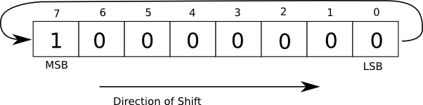
The image below shows the operation of an 8-bit ring counter as implemented in VHDL in this tutorial.
Ring Counter in VHDL Code
The code below is a modified version of one of the shift registers from the previous tutorial.
library IEEE;
use IEEE.STD_LOGIC_1164.ALL;
use IEEE.STD_LOGIC_UNSIGNED.ALL;

entity ring_counter_top is
    Port ( CLK : in   STD_LOGIC;
           LED : out  STD_LOGIC_VECTOR (7 downto 0));
end ring_counter_top;

architecture Behavioral of ring_counter_top is
    signal clock_div : STD_LOGIC_VECTOR(4 downto 0);
    --signal shift_reg : STD_LOGIC_VECTOR(7 downto 0) := X"80";
    signal shift_reg : STD_LOGIC_VECTOR(7 downto 0) := X"7F";
begin

    -- clock divider: slows clock to make LEDs visible
    process (CLK)
    begin
        if (CLK'event and CLK = '1') then
            clock_div <= clock_div + '1';
        end if;
    end process;

    -- ring counter
    process (clock_div(4))
    begin
        if (clock_div(4)'event and clock_div(4) = '1') then
            shift_reg(7) <= shift_reg(0);
            shift_reg(6) <= shift_reg(7);
            shift_reg(5) <= shift_reg(6);
            shift_reg(4) <= shift_reg(5);
            shift_reg(3) <= shift_reg(4);
            shift_reg(2) <= shift_reg(3);
            shift_reg(1) <= shift_reg(2);
            shift_reg(0) <= shift_reg(1);
        end if;
    end process;

    -- hook up the ring counter register bits to the LEDs
    LED <= shift_reg;

end Behavioral;
Initializing the Shift Register
The shift register (shift_reg) is first initialized to set the MSB in the shift register with this code:
signal shift_reg : STD_LOGIC_VECTOR(7 downto 0) := X"80";
This writes 1000-0000b to shift_reg.
In the code, the shift register is wired to the LEDs so that each bit in the shift register can be seen on the LEDs interfaced to the CPLD (8 bits in the register interface to 8 LEDs):
LED <= shift_reg;
Because the LEDs on the home built CPLD board are wired as current sinking, initializing shift_reg (and therefore the LEDs) with 1000-0000b will switch the MSB LED off and all the other LEDs on. This line of code is therefore commented out and the first bit is cleared with all the other bits set:
--signal shift_reg : STD_LOGIC_VECTOR(7 downto 0) := X"80";
signal shift_reg : STD_LOGIC_VECTOR(7 downto 0) := X"7F";
Now 0111-1111b is written to shift_reg.
Ring Counter Operation
Instead of feeding data into the shift register on one end and shifting the data out of the shift register on the other end, the ring counter code shifts the data in the shift register to the right, but also shifts the last bit (bit 0) back to the first bit (bit 7) thus completing the ring:
shift_reg(7) <= shift_reg(0);
Like the shift register in tutorial 11, the rest of the code in the VHDL process shifts every bit to the right.
Implementing the Ring Counter using ror
The VHDL ror (rotate right logical) operator can be used to rotate data to the right, rather than just shifting it. Using the ror operator on a register implements a ring counter.
The following code shows how to use the VHDL ror operator in a ring counter.
library IEEE;
use IEEE.STD_LOGIC_1164.ALL;
use IEEE.STD_LOGIC_UNSIGNED.ALL;

entity ring_counter_ror_top is
    Port ( CLK : in   STD_LOGIC;
           --LED : out  STD_LOGIC_VECTOR (7 downto 0)); -- can't use
           LED : out  BIT_VECTOR (7 downto 0));
end ring_counter_ror_top;

architecture Behavioral of ring_counter_ror_top is
    signal clock_div : STD_LOGIC_VECTOR(4 downto 0);
    signal shift_reg : BIT_VECTOR(7 downto 0) := X"7F";
begin

    -- clock divider
    process (CLK)
    begin
        if (CLK'event and CLK = '1') then
            clock_div <= clock_div + '1';
        end if;
    end process;

    -- ring counter
    process (clock_div(4))
    begin
        if (clock_div(4)'event and clock_div(4) = '1') then
            shift_reg <= shift_reg ror 1;     -- rotate right
            --shift_reg <= shift_reg rol 1;     -- rotate left
            --shift_reg <= shift_reg srl 1;     -- shift right logical
            --shift_reg <= shift_reg sll 1;     -- shift left logical
        end if;
    end process;

    -- hook up the LEDs to the ring counter bits
    LED <= shift_reg;

end Behavioral;
Using ror
The first thing to note is that ror can't operate on the STD_LOGIC_VECTOR data type. The shift register shift_reg has to be defined using the BIT_VECTOR data type instead.
signal shift_reg : BIT_VECTOR(7 downto 0) := X"7F";
Because we want to wire the bits in shift_reg to the LEDs, we need to make LED of the BIT_VECTOR data type as well:
LED : out BIT_VECTOR (7 downto 0)
Which is in the entity part of our VHDL file:
entity ring_counter_ror_top is
    Port ( CLK : in   STD_LOGIC;
           --LED : out  STD_LOGIC_VECTOR (7 downto 0)); -- can't use
           LED : out  BIT_VECTOR (7 downto 0));
end ring_counter_ror_top;
If the two vectors were not of the same type, then we would not be able to do this:
LED <= shift_reg;
The synthesis step of compiling the VHDL code would give an error.
The ror operator works by rotating x to the right by n number of bits and stores the result in y:
y <= x ror n;
VHDL Shift Operators
There are six shift operators in VHDL:
- rol – rotate left logical
- ror – rotate right logical
- sll – shift left logical
- srl – shift right logical
- sla – shift left arithmetic
- sra – shift right arithmetic
Four of these operators have been included in the above code listing (the ring_counter_ror_top code) to demonstrate their operation. Uncomment any one of the statements containing a shift operator and comment all of the others out. Compile and load the code to a CPLD board to see the operators working.
The sll and srl operators shift the data in the shift register out of the shift register and shift 0's in on the other end. The 0's will switch the LEDs on when using the home built CPLD board.
VHDL Data Types
We have now seen that there is more than one data type in VHDL. The VHDL code so far in this course has used the STD_LOGIC_VECTOR data type (for more than one bit), the STD_LOGIC data type (for a single bit) and now the BIT_VECTOR data type.
In the next tutorial in this series, we will look at VHDL data types in more detail.