Donations help to keep the site running:
Home
![]() Tutorials
Tutorials
![]() AVR 8 Microcontrollers
AVR 8 Microcontrollers
![]() ATtiny2313 Tutorial
ATtiny2313 Tutorial
![]() P9 TC0 Interrupt Timer
P9 TC0 Interrupt Timer
Timer Interrupt using Timer/Counter0 (TC0)
Created on: 1 May 2013
Part 9 of the ATtiny2313 Tutorial
Timer/Counter0 (TC0) of the ATtiny2313 is set up as a timer. When the set time period has elapsed, an interrupt will occur.
An ISR (Interrupt Service Routine) will be run when the interrupt occurs. All software including the ISR are written in C.
In this example, the timer interrupt is used to toggle an LED.
Circuit Diagram
Use the same circuit diagram from the previous part of this tutorial – open the circuit diagram.
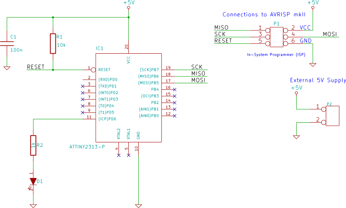
Software
The C source code is shown here.
#include <avr/io.h>
#include <avr/interrupt.h>

int main(void)
{
    DDRD |= (1 << PD6); // LED on PD6

    OCR0A  = 0x70;      // number to count up to (0x70 = 112)
    TCCR0A = 0x02;      // Clear Timer on Compare Match (CTC) mode
    TIFR |= 0x01;       // clear interrupt flag
    TIMSK = 0x01;       // TC0 compare match A interrupt enable
    TCCR0B = 0x05;      // clock source CLK/1024, start timer

    sei();              // global interrupt enable

    while(1)
    {
        // do nothing here, the ISR toggles the LED
    }
}

// interrupt service routine (ISR) for timer 0 A compare match
SIGNAL (SIG_TIMER0_COMPA)
{
    static char toggle = 0;

    // toggle the LED on each interrupt
    if (toggle) {
        toggle = 0;
        PORTD &= ~(1 << PD6);
    }
    else {
        toggle = 1;
        PORTD |=  (1 << PD6);
    }
}
The timer is operated in the same way as explained in the previous part of this tutorial, except that the time period has been shortened.
Handling Interrupts in C
Each C compiler will differ in the way that interrupt service routines (ISRs) are set up. The above code is for setting up an ISR using the GNU compiler used with Atmel Studio 6.
Header File
The interrupt header file must be included when using interrupts in C:
#include <avr/interrupt.h>
Enabling Interrupts
Before enabling an interrupt for a timer 0 compare match, the timer compare match A interrupt flag is cleared as a precaution:
TIFR |= 0x01; // clear interrupt flag
The compare match A interrupt enable bit is then set:
TIMSK = 0x01; // TC0 compare match A interrupt enable
No interrupt will work until the global interrupt enable flag is set:
sei(); // global interrupt enable
This will then enable all individually enabled interrupts. In the above code, only the compare match A interrupt is enabled and will therefore be the only interrupt that is operating after the global interrupt enable flag is set.
Interrupt Service Routine (ISR)
An ISR is specified using SIGNAL as the ISR function name for the GNU compiler:
SIGNAL (SIG_TIMER0_COMPA)
{
    // ISR code goes here
}
In the above code, the ISR is specified to be called when timer 0 generates a compare A interrupt by using SIG_TIMER0_COMPA.
Timer Period and Frequency
For this example, the timer time period and frequency are calculated the same way as was done in the previous part of this tutorial. Assuming the ATtiny2313 clock is at its default frequency of 1MHz, the timer will toggle the LED at a frequency of:
1MHz ÷ 1024 ÷ 112 ÷ 2 = 4.36Hz
Where:
1MHz = clock frequency
1024 = prescaler clock source selected for timer 0
112 = value to count up to (0x70)
2 = 2 time periods for one LED on/off cycle
The timer time period is:
1 ÷ (1MHz ÷ 1024 ÷ 112) = 114.688ms
Because the LED uses two of these time periods, one for its on time and one for its off time, a complete LED on/off cycle will be:
114.688ms × 2 = 229.376ms
frequency = 1 ÷ time
frequency of LED = 1 ÷ 229.376ms = 4.36Hz (same as above)
Atmel Studio Source Code
The C source code for this part of the tutorial can be copied and pasted from the above listing, or the entire Atmel Studio 6 project can be downloaded here:
TC0_interrupt_timer.zip (15.7kB)