Donations help to keep the site running:
Home
![]() Tutorials
Tutorials
![]() AVR 8 Microcontrollers
AVR 8 Microcontrollers
![]() ATtiny2313 Tutorial
ATtiny2313 Tutorial
![]() P11 PWM
P11 PWM
ATtiny2313 PWM – Pulse Width Modulation
Created on: 6 May 2013
Part 11 of the ATtiny2313 Tutorial
Timer/Counter0 of the ATtiny2313 is used to generate a PWM (Pulse Width Modulation) waveform. PWM is demonstrated by using it to brighten and dim an LED.
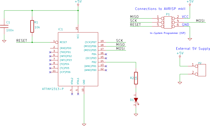
Circuit Diagram
The PWM output is obtained from the OC0A output of timer/counter0 which is on PB2, pin 14 of the ATtiny2313.
Stepped PWM Example
This example changes the PWM value (and therefore the pulse width) every two seconds. This causes the LED to change to a different brightness every two seconds.
Software
// TC0_PWM.c
#define F_CPU 1000000UL
#include <avr/io.h>
#include <util/delay.h>

int main(void)
{
    DDRB   |= (1 << PB2);                   // PWM output on PB2
    TCCR0A = (1 << COM0A1) | (1 << WGM00);  // phase correct PWM mode
    OCR0A  = 0x10;                          // initial PWM pulse width

    TCCR0B = (1 << CS01);   // clock source = CLK/8, start PWM

    while(1)
    {
        // change PWM pulse width every 2 seconds
        _delay_ms(2000);
        OCR0A  = 0x10;
        _delay_ms(2000);
        OCR0A  = 0x30;
        _delay_ms(2000);
        OCR0A  = 0x50;
        _delay_ms(2000);
        OCR0A  = 0xA0;
    }
}
Before using the PWM, the output pin from the PWM must be set as an output. This pin is PB2 which has the alternate function of output from Timer/Counter 0:
DDRB |= (1 << PB2); // PWM output on PB2
Timer/Counter0 is then put into phase correct PWM mode, set with an initial value and started.
Writing to the OCR0A will change the width of the PWM pulse.
Project Source Code
The source code above can be copied and pasted to your own project, or download the Atmel Studio project for this example here:
TC0_PWM.zip (14.8kB)
Continuous PWM Example
This example fades the LED from dim to bright and then back to dim continuously.
Software
//TC0_PWM_fade.c
#define F_CPU 1000000UL
#include <avr/io.h>
#include <util/delay.h>

int main(void)
{
    unsigned char PWM_val = 0;		// 8-bit PWM value
    unsigned char up_dn = 0;		// up down count flag

    DDRB   |= (1 << PB2);                   // PWM output on PB2
    TCCR0A = (1 << COM0A1) | (1 << WGM00);  // phase correct PWM mode
    TCCR0B = (1 << CS01);   // clock source = CLK/8, start PWM

    while(1)
    {
        if ((PWM_val == 255) || (PWM_val == 0)) {
            up_dn ^= 0x01;      // toggle count direction flag
        }
        _delay_ms(5);
        OCR0A  = PWM_val;       // write new PWM value
        if (up_dn) {            // increment or decrement PWM value
            PWM_val++;
        }
        else {
            PWM_val--;
        }
    }
}
By incrementing the value written to the OCR0A every 5ms, the brightness of the LED is increased smoothly. When the maximum value (255) that can be written to OCR0A is reached, the value is decremented every 5ms, smoothly dimming the LED.
The PWM in this example is set up in the same phase correct PWM mode as the previous example.
Project Source Code
The source code above can be copied and pasted to your own project, or download the Atmel Studio project for this example here:
TC0_PWM_fade.zip (15.3kB)