Donations help to keep the site running:
Home
![]() Tutorials
Tutorials
![]() AVR 8 Microcontrollers
AVR 8 Microcontrollers
![]() ATtiny2313 Tutorial
ATtiny2313 Tutorial
![]() P13 TC1 Polled Timer
P13 TC1 Polled Timer
Polling 16-bit Timer/Counter1 in Software
Created on: 14 May 2013
Part 13 of the ATtiny2313 Tutorial
The ATtiny2313 has a 16-bit timer/counter module – timer/counter1 (TC1). TC1 is set up to create a timing period for flashing an LED. The timer flag set when the timing period is up is polled in software using a program written in C.
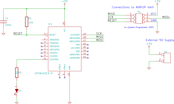
Circuit Diagram
The same circuit used in previous parts of this tutorial is used here again. An LED is interfaced to pin 11 of the ATtiny2313.
C Software Program & Source Code
The C program for this example is shown here.
#include <avr/io.h>

int main(void)
{
    char toggle = 0;        // toggle LED flag

    DDRD |= (1 << PD6);     // LED on PD6

    OCR1A = 0x4000;         // number to count to
    TCCR1A = 0;             // CTC mode
    // CTC mode, clk src = clk/8, start timer
    TCCR1B = (1 << WGM12) | (1 << CS11);

    while(1)
    {
        if (TIFR & (1 << OCF1A)) {  // count reached?
            TIFR |= (1 << OCF1A);   // clear flag
            if (toggle) {           // toggle LED
                toggle = 0;
                PORTD &= ~(1 << PD6);
            }
            else {
                toggle = 1;
                PORTD |=  (1 << PD6);
            }
        }
    }
}
Atmel Studio Project Source Code
Either copy and paste the above C source code to your own project or download the Atmel Studio 6 project including source code and output files here:
TC1_polled_timer.zip (14.9kB)
How the Program Works
The program works the same way as the example from Timer/Counter0 (TC0) Polled Timer (part 8 of this tutorial), but the timer register and compare register are each 16-bits wide.
By setting the timer/counter into CTC mode, the count value will be cleared when the maximum count value is reached. The maximum count value is set in the OCR1A register:
OCR1A = 0x4000; // number to count to
The timer/counter in this example counts up to 0x4000 or 16384.
The clock source for the timer is taken from the prescaler and is the system clock frequency divided by 8. The timing period is generated by the timer counting from 0 to 0x4000 and then setting the OCF1A bit in the TIFR register.
Note that the TIFR register is shared by both timer/counter0 and timer/counter1. In this register, some bits apply to TC0 and others to TC1 as described in the ATtiny2313 datasheet.
Timing Period of Timer
The timing period for the timer can be calculated by using the formula:
f = fclk ÷ (2 × N × (1 + OCR1A))
Where:
- f = timer frequency
- fclk = system clock frequency
- N = prescaler division factor
- OCR1A = value in OCR1A register
Assuming that the system clock frequency is the default 1MHz derived from the internal R/C oscillator, the frequency of the flashing LED in the above code example can be calculated as follows:
f = 1MHz ÷ (2 × 8 × (1 + 16384)) = 3.814Hz