Donations help to keep the site running:
Home
![]() Tutorials
Tutorials
![]() AVR 8 Microcontrollers
AVR 8 Microcontrollers
![]() ATtiny2313 Tutorial
ATtiny2313 Tutorial
![]() P8 TC0 Polled Timer
P8 TC0 Polled Timer
ATtiny2313 Timer/Counter0 (TC0) Polled Timer Tutorial
Created on: 29 April 2013
Part 8 of the ATtiny2313 Tutorial
Timer/Counter0 (TC0) of the ATtiny2313 is set up as a timer and then polled to see when the time period is complete. To demonstrate the timer time period, a LED is switched on for the timer time period and then off for the timer time period continually.
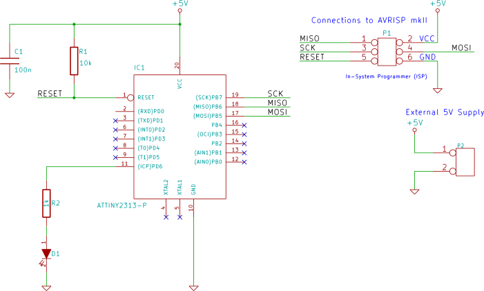
Circuit Diagram
The circuit used for this part of the tutorial is simply an LED interfaced to pin 11 of the ATtiny2313.
Software
The C source code for this example is shown below.
#include <avr/io.h>

int main(void)
{
    char toggle = 0;

    DDRD |= (1 << PD6); // LED on PD6

    TCCR0A = 0x02;      // Clear Timer on Compare Match (CTC) mode
    OCR0A  = 0xFF;      // number to count up to
    TCCR0B = 0x05;      // clock source CLK/1024, start timer

    while(1)
    {
        if (TIFR & 0x01) {      // timer timed out?
            TIFR |= 0x01;       // reset timer flag
            // toggle LED each time the timer times out
            if (toggle) {
                toggle = 0;
                PORTD &= ~(1 << PD6);
            }
            else {
                toggle = 1;
                PORTD |=  (1 << PD6);
            }
        }
    }
}
The timer is first set up and started. In the while(1) loop, the timer is continually polled to see if it has timed out.
When the timer has timed out, the LED is toggled (switched on if it is off, or switched off if it is on) and the timer output compare flag is reset.
Timer
Timer/Counter0 on the ATtiny2313 is an 8-bit device.
Timer Clock Source
The clock source of TC0 is selected using the TCCR0B register (Timer/Counter Control Register B). Bits 2 to 0 of this register select the clock source. Setting these bits to 0 selects no clock source and stops the counter/timer.
In the above code, this register is set to 0x05 which selects the clock source as the master clock divided by 1024 from the prescaler.
OCR0A Register
OCR0A is the output compare register A. The counter will count up to the value in this register and then trigger.
In the source code, this register is set to its maximum value of 0xFF (or 255).
TIFR Register
The TIFR (Timer/Counter Interrupt Flag Register) contains the OCF0A bit (bit 0) which will be set when the current count value matches the value in the OCR0A register.
This bit is continually polled to see if it is set:
if (TIFR & 0x01) { // timer timed out?
To clear the bit, 1 is written to it:
TIFR |= 0x01; // reset timer flag
After clearing the bit, it can be polled again to see when the next time period has elapsed.
Timer Mode
The timer is put into CTC mode (Clear Timer on Compare Match) using the TCCR0A register so that the count value will be cleared when the count value matches the value in the OCR0A register:
TCCR0A = 0x02; // Clear Timer on Compare Match (CTC) mode
In this example, it makes no difference if this register is left in its default state as the counter will then automatically count to its maximum value of 0xFF (or 255) and the value set in OCR0A will be ignored.
If you want to make a shorter time period, then it is necessary to set the timer to CTC mode using the TCCR0A register so that when the count value matches the value in OCR0A, the count value will be reset.
Time Period
With the current system clock of the ATtiny2313 at its default value (1MHz) as explained in the previous part of this tutorial, and the clock source for the timer/counter selected as the master clock divided by 1024 from the prescaler, the timer/counter will be clocked by:
1MHz ÷ 1024 = 976.563Hz
With the timer/counter counting up to 255 (0xFF), the period of the timer will be:
976.563Hz ÷ 255 = 3.83Hz
Period = 1 ÷ 3.83Hz = 261.12ms
Because we are toggling the LED every 261.12ms, the period of one on-off cycle of the LED (or one clock pulse) will be twice the period of the timer:
522.24ms
The frequency of the LED is then:
1 ÷ 522.24ms = 1.915Hz
Atmel Studio Source Code
The C source code for this part of the tutorial can be copied and pasted from the above listing, or the entire Atmel Studio 6 project can be downloaded here:
TC0_polled_timer.zip (14.7kB)