
A 555 tone generator circuit is a simple electronics project that uses a 555 timer IC to produce an audible tone through a loudspeaker. This beginner-friendly circuit uses just a few components, including two resistors, three capacitors, a 555 timer and an 8-ohm speaker. Powered by a 9V supply, it generates a continuous audio tone of approximately 700 to 750Hz.
The circuit is useful for learning how the 555 timer works as an oscillator, and it is one of several easy 555 timer projects that can be built on a solderless breadboard. With a few modifications, the same basic design can also be used in warning devices, simple alarms and other audio experiments.
What Is a 555 Tone Generator Circuit?
A 555 tone generator circuit is an electronic circuit that uses a 555 timer IC in astable mode (oscillator mode) to generate a repeating electrical waveform. The waveform appears at the timer’s output pin and produces sound when applied to a suitable speaker.
The circuit described in this article generates a continuous tone rather than a changing siren sound. Although it can be used as a basic audible warning device, it does not automatically sweep between high and low frequencies like a conventional electronic siren. The following video demonstrates the circuit.
The main features of this circuit are:
- Simple construction: Only a handful of inexpensive components are required.
- 9V operation: The circuit is designed around a 9V supply.
- Audible output: An 8-ohm speaker reproduces the tone.
- Adjustable frequency: Changing the timing resistor or capacitor values changes the output frequency.
- Beginner-friendly design: The circuit demonstrates the basic operation of a 555 timer oscillator.
This audio tone generator circuit is a good starting point for anyone learning about electronic oscillators, timing circuits and audio signals.
555 Tone Generator Circuit Diagram
The circuit operates from a 9V DC supply and uses the 555 timer to produce a square-wave output. The output is coupled to an 8-ohm speaker through a 100µF capacitor.
The timing components determine the tone frequency. A 1kΩ resistor, a 100kΩ resistor and a 10nF capacitor form the main timing network. Below is the circuit diagram for this circuit.
You can use the 555 chip pinout article as a reference for the pin numbers and functions on the physical 8-pin DIP 555 IC.
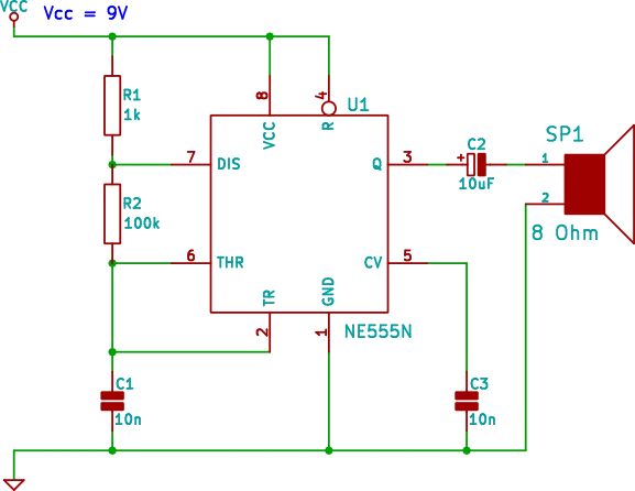
The circuit connections are as follows:
- Pin 8 connects to the positive 9V supply, labeled Vcc.
- Pin 1 connects to ground.
- Pin 4, the RESET pin, must be held high for continuous operation. Connect it to the positive supply.
- Pin 7 connects to the positive supply through R1, a 1kΩ resistor.
- Pin 7 connects to pins 2 and 6 through R2, a 100kΩ resistor.
- Pins 2 and 6 connect together.
- C1, a 10nF capacitor, connects between pins 2 and 6, and ground.
- Pin 5 connects to ground through C3, a 10nF capacitor.
- Pin 3 connects through C2, a 100µF capacitor, to one terminal of SP1, an 8-ohm speaker.
- The other speaker terminal connects to ground.
Important circuit check: Make sure pin 4 is connected to the positive supply. The RESET pin should not be left floating, because doing so can prevent reliable oscillation.
The 100µF output capacitor should be an electrolytic type. Observe its polarity, with the positive terminal facing the 555 output and the negative terminal facing the speaker.
Components Required for the 555 Tone Generator Circuit
The following table lists the main components needed to build the circuit. A standard 8-pin NE555 timer is suitable for this project. Check the datasheet for your particular device to confirm its operating-voltage limits and output-drive specifications.
You will also need a breadboard or another suitable construction method. A regulated bench supply can be useful during testing, although a suitable 9V battery is convenient for a portable demonstration.
| Component | Value or Type | Purpose |
|---|---|---|
| U1 | NE555 or compatible 555 timer | Generates the audio waveform |
| R1 | 1 kΩ resistor | Sets the charging current for the timing capacitor C1 |
| R2 | 100kΩ resistor | Helps determine the oscillation frequency |
| C1 | 10nF capacitor | Main timing capacitor |
| C2 | 100µF electrolytic capacitor | Couples the output signal to the speaker |
| C3 | 10nF capacitor | Filters noise at the control-voltage pin |
| SP1 | 8-ohm speaker | Converts the electrical signal into sound |
| Power supply | 9V DC | Powers the circuit |
| Breadboard and jumper wires | Suitable for the circuit | Allow the circuit to be assembled and tested |
How the 555 Tone Generator Circuit Works
The 555 timer is configured as an astable oscillator. In astable mode, the timer repeatedly switches its output between high and low without requiring an external trigger for every cycle.
The timing capacitor C1 charges and discharges through the resistors R1 and R2 connected to the 555 timer. As its voltage crosses the timer’s internal switching thresholds, the output changes state.
This process repeats continuously, producing a square wave at pin 3. The output waveform contains the alternating voltage changes needed to create an audible tone.
The Role of the Timing Resistors
R1 and R2 control how quickly C1 charges and discharges.
R1 is 1kΩ, while R2 is 100kΩ. Because R2 is much larger than R1, it has the greatest influence on the oscillation period in this circuit.
Increasing R2 generally lowers the tone frequency. Decreasing R2 generally raises it.
The Role of the Timing Capacitor
C1 is a 10nF capacitor connected between the joined pins 2 and 6, and ground.
The 555 timer monitors the voltage across this capacitor. When the voltage reaches its upper threshold, the timer changes state and the capacitor begins discharging. When the voltage falls to the lower threshold, the timer switches again and charging resumes.
The repeated charging and discharging action creates the continuous oscillation.
The Role of the Output Capacitor
C2 is a 100µF capacitor connected in series with the speaker.
The capacitor couples the changing audio signal to the speaker while blocking the steady DC component of the output. This helps prevent continuous DC current from flowing through the speaker.
The speaker responds to the alternating signal by moving its cone back and forth, producing sound.
The Role of C3
C3 is a 10nF capacitor connected between pin 5 and ground. Pin 5 is the 555 timer’s control-voltage input.
This capacitor helps reduce noise and unwanted interference at the control-voltage input, supporting stable operation.
Calculating the Tone Frequency
The approximate oscillation frequency of a 555 timer operating in astable mode can be calculated using:
Where:
- is the output frequency in hertz.
- is the first timing resistor in ohms.
- is the second timing resistor in ohms.
- is the timing capacitor in farads.
For this 555 tone generator circuit, the values are:
Substituting these values gives:
The calculated frequency is approximately 716 Hz. The actual frequency may differ because of resistor tolerances, capacitor tolerances, the characteristics of the 555 timer and the circuit’s operating conditions.
A frequency of around 700 Hz is clearly audible and suitable for a simple tone generator.
Building the 555 Tone Generator Circuit on a Breadboard
A solderless breadboard makes it easy to assemble this simple tone generator circuit and change components during experimentation.
Follow these steps to build it.
- Insert the 555 timer. Place the IC across the center gap of the breadboard so that each row of pins remains separate.
- Connect the power supply. Connect pin 8 to the positive 9V rail and pin 1 to the ground rail.
- Connect RESET. Connect pin 4 to the positive supply so that the timer remains enabled.
- Add the timing resistors. Connect R1, the 1kΩ resistor, between the positive supply and pin 7. Connect R2, the 100 kΩ resistor, between pin 7 and the joined pins 2 and 6.
- Install C1. Connect the 10nF timing capacitor between the joined pins 2 and 6 and ground.
- Install C3. Connect the other 10nF capacitor between pin 5 and ground.
- Connect the speaker. Connect pin 3 through C2, the 100µF capacitor, to the 8-ohm speaker. Connect the other speaker terminal to ground.
- Inspect the wiring. Check the IC orientation, resistor connections, capacitor polarity and power rails.
- Apply power. Connect the 9V supply and listen for the continuous tone.
Keep the power switched off while changing connections. If the circuit does not work, disconnect the supply before inspecting the wiring.
Adjusting the 555 Tone Generator Circuit
One of the advantages of a 555 timer is that the tone can be changed by adjusting the timing components. You can experiment with different values to explore the relationship between resistance, capacitance and frequency.
| Component Change | Expected Result |
|---|---|
| Increase R2 | Lower tone frequency |
| Decrease R2 | Higher tone frequency |
| Increase C1 | Lower tone frequency |
| Decrease C1 | Higher tone frequency |
| Use a suitable audio amplifier | Greater output volume, depending on the design |
For example, replacing C1 with a 22nF capacitor should lower the frequency considerably. Reducing C1 to 4.7nF should raise the frequency.
The exact result depends on the complete timing network consisting of R1, R2, and C1, so calculate the expected frequency before selecting replacement components.
When experimenting, change one component at a time. This makes it easier to understand how each component affects the sound.
Using the 555 Tone Generator Circuit as a Warning Device
The circuit can produce a continuous warning tone that is useful for demonstrations and basic electronic experiments.
Possible applications include:
- A simple audible indicator in a learning project.
- A demonstration of electronic oscillators.
- Basic tone source for testing audio circuits.
- An experimental sound generator for a model or hobby project.
- A starting point for building an electronic alarm.
However, this design produces a constant tone. It does not generate a sweeping siren sound on its own.
To create a rising and falling siren, you could add another oscillator or modulation stage to vary the timing resistance or control voltage. A second 555 timer is one possible way to generate the slower modulation signal.
If you intend to use the circuit as a practical alarm, consider its volume, reliability, power consumption and the requirements of the application.
Troubleshooting the 555 Tone Generator Circuit
If the speaker does not produce a sound, check the circuit systematically.
| Problem | Possible Cause | Suggested Solution |
|---|---|---|
| No sound | Incorrect wiring | Compare every connection with the schematic |
| No sound | Pin 4 is floating or held low | Connect RESET to the positive supply |
| No sound | Incorrect IC orientation | Check the notch or pin 1 marking |
| No sound | Reversed or faulty output capacitor | Check C2 polarity and condition |
| Very quiet sound | Speaker is inefficient or output drive is limited | Check the speaker and consider a suitable transistor driver |
| Tone is too high or low | Incorrect timing resistor or capacitor | Verify component values and tolerances |
| Unstable tone | Poor power connections or noisy supply | Improve wiring and supply decoupling |
| Distorted sound | The 555 output is overloaded | Reduce the load or add an appropriate output stage |
An 8-ohm speaker is a relatively low-impedance load. Although a 555 timer can drive small loads, the available output current and safe operating conditions depend on the specific timer, supply voltage and waveform. Do not assume every 555 variant can safely drive a speaker at high volume.
If you need more sound output, a transistor or audio amplifier stage can be added between the timer and the speaker. Select the driver and its components according to the speaker impedance and required output power.
Tips for 555 Tone Generator Circuit Construction
These practical tips can help you build and test the circuit successfully.
- Check the 555 pin numbers carefully. The 555 chip pinout is easy to misread when the IC is rotated on a breadboard.
- Use the correct capacitor values. A 10nF capacitor is not the same as a 10µF capacitor. Check the markings before installation.
- Keep the timing connections short. Short connections can help reduce unwanted interference and make the circuit easier to troubleshoot.
- Check electrolytic capacitor polarity. The 100µF output capacitor must be installed in the intended direction.
- Connect RESET correctly. Pin 4 should be held high for continuous operation.
- Start with a 9V supply. This is the specified supply for the circuit and provides a convenient reference for testing.
- Do not expect a loud alarm from every speaker. The circuit is intended as a simple audio experiment, and the output volume depends on the speaker and the timer’s drive capability.
- Change one component at a time. This makes it easier to learn how the circuit’s frequency responds to changes in resistance and capacitance.
The best approach is to get the basic circuit working first, then experiment with alternative timing values or an additional output stage.
Did You Know?
The 555 timer was introduced in the early 1970s and became one of the most widely used integrated circuits in electronics. Its versatility comes from the ability to configure it for timing, pulse generation and oscillation using a small number of external components.
The same basic astable configuration used in this project can generate signals at frequencies ranging from slow flashes to audible tones and much higher frequencies, depending on the component values and the particular device.
The 555 is also used in LED flashers, pulse generators, timers, simple musical instruments and many other beginner projects.
An important distinction is that a square wave contains a fundamental frequency and harmonics. As a result, the sound from a 555 timer may have a more buzzy quality than a pure sine-wave tone at the same frequency.
That characteristic makes the 555 a useful teaching tool for exploring both electronic signals and the sounds they produce.
Frequently Asked Questions
What frequency does this 555 tone generator circuit produce?
Using the specified 1kΩ and 100kΩ resistors with a 10nF timing capacitor, the standard astable formula gives approximately 716Hz. Component tolerances and operating conditions can cause the measured frequency to differ.
Can I power the circuit with a 9V battery?
Yes. A suitable 9V battery can power this circuit, provided the timer and all other components are compatible with the supply voltage. Battery life depends on the current drawn, especially by the speaker.
Can I use a different 555 timer IC?
In many cases, yes. An NE555 or a compatible 555 timer can be suitable, but check the datasheet for the particular device. Different bipolar and CMOS versions have different output-drive capabilities and operating characteristics.
Can I change the tone frequency?
Yes. Changing R2 or C1 changes the oscillation frequency. Increasing either value lowers the frequency, while decreasing either value raises it, assuming the other components remain unchanged.
Why is the speaker volume low?
The 555 output may not provide enough current to drive the particular speaker at a high volume. Speaker efficiency, supply voltage and the timer’s output-drive limits all affect the sound level. A suitable transistor driver or audio amplifier can provide greater output.
Does this circuit produce an electronic siren sound?
No. In its basic form, it produces a continuous tone. A siren effect requires the frequency to change over time, which can be achieved by adding a modulation circuit or another oscillator.
Can I build this circuit without soldering?
Yes. A solderless breadboard is suitable for assembling and testing the circuit. Make sure the connections are secure and that the power is disconnected whenever you modify the wiring.
What does C2 do in the circuit?
C2 is the 100µF output coupling capacitor. It allows the changing audio signal to reach the speaker while blocking the steady DC component of the 555 output.
What is the purpose of C3?
C3 is connected between pin 5 and ground. It helps filter noise at the control-voltage input, which can improve circuit stability.
Conclusion
This 555 tone generator circuit is a practical beginner electronics project that demonstrates how a 555 timer can generate an audible signal using a small number of inexpensive components. With a 9V supply, a 1kΩ resistor, a 100kΩ resistor and a 10nF timing capacitor, the circuit produces a tone of approximately 716Hz through an 8-ohm speaker.
The project is useful for learning about astable oscillators, timing components, output coupling capacitors and basic audio signals. Once the circuit is working, you can experiment with different component values, measure the output frequency or add a driver stage to increase the speaker volume.
For anyone exploring easy 555 timer projects, this simple tone generator circuit provides a useful foundation for more advanced audio oscillators, alarms and electronic sound effects.
Other 555 timer IC circuits and projects: