
A 555 project is an excellent way for beginners to learn practical electronics by building a working circuit. In this tutorial, you will assemble a running LED light display using a 555 timer IC, a CD4017BE decade counter, and an electronic solder kit. The circuit switches ten LEDs on one at a time, creating the appearance of a light moving along a row. When the sequence returns to the first LED, an eleventh LED flashes independently for a period of time. It is also possible to build this circuit on an electronic breadboard.
This project is particularly useful for learning how to identify electronic components, solder them onto a printed circuit board (PCB), connect a DC power supply, and troubleshoot a completed circuit. The kit also introduces two widely used integrated circuits that feature in many beginner electronics projects.
What Is a 555 Project Running Light Display?
A 555 project running light display is an electronic circuit that turns LEDs on and off in a repeating sequence. This particular kit uses a 555 timer IC to generate clock pulses and a CD4017BE decade counter IC (Integrated Circuit) to select which LED lights up next. The video below shows the finished kit powered up and running.
The kit is designed for beginners who want to build a practical electronic circuit without having to design a PCB or source every component individually. The supplied circuit board has positions marked for the components, making assembly straightforward once you understand the basic soldering process. Of course you need to know how to use a soldering iron to build this project. Below is an image of the circuit board and electronic components from the kit.
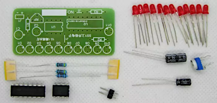
The main features of this 555 project are:
- Ten red LEDs light up in sequence, with only one LED on at a time.
- The sequence moves in one direction from the first LED to the tenth LED.
- After the tenth LED, the sequence returns to the first LED and repeats.
- An eleventh LED flashes on and off independently for a period of time when the main sequence returns to the first LED.
- A trimmer potentiometer lets you adjust the speed of the running light.
- The circuit operates from a DC supply between 3.3V and 12V, according to the kit specifications.
- It was tested with a 9V battery and worked fine.
- It was also tested with two 1.2V rechargeable cells in a battery holder which gave a total of 2.7V when fully charged.
Although it is a type of LED chaser circuit, it is not a Knight Rider display. A traditional Knight Rider-style display moves back and forth along the LEDs, whereas this circuit restarts at the first LED after reaching the last one.
Also note that there are different variations of this same kit, so if you have a kit that is similar, the build instructions are going to be very close, if not the same to this project. The kit ordered for this project is actually different from the kit shown on the electronic store’s website where it was bought. On the website, the kit has 10 LEDs only, and the 11th LED is not present at all. The particular electronic kit used in this tutorial has the part number or product code 555-4017-DIP-KIT, and description: Running Light 555 + 4017 Dip Kit.
How the 555 Project Circuit Works
This 555 IC project uses two integrated circuits to produce the running light effect. Each IC performs a different task, and understanding their roles makes the circuit easier to troubleshoot and modify.
NE555P Timer IC (U1)
The NE555 timer generates a repeating series of electrical pulses, known as a clock pulse. These pulses determine how quickly the LEDs change. The trimmer potentiometer adjusts the timing, allowing you to make the running light move faster or slower. A NE555P IC from Texas Instruments is specified to work from 4.5V to 16V. Different manufacturers of this same part may specify different minimum and maximum operating voltages. The kit was tested and worked at a voltage as low as 2.7V even with the NE555P that came with the kit. It is unknown which manufacturer this kit IC came from.
CD4017BE Decade Counter IC (U2)
The CD4017BE responds to the clock pulses from the 555 timer. It activates its outputs in sequence, allowing the circuit to switch between the ten main LEDs. Once the sequence reaches its final state, the circuit resets to the beginning. A Texas Instruments CD4017BE is specified to work from voltages between 3V to 18V. Despite the recommended minimum operating voltage being 3V, the kit still worked with a 2.7V supply voltage.
The 555 timer and CD4017BE are often used together in beginner electronics because they provide a simple way to turn a repeating timing signal into a visible sequence of outputs.
The role of the 555 timer
The NE555P operates as an oscillator in this circuit. Rather than producing just one output pulse, it repeatedly switches its output between low and high voltage levels.
Each pulse advances the CD4017BE counter by one step. Changing the timing components’ effective resistance changes the pulse frequency, which changes the speed of the display.
The role of the CD4017BE
The CD4017BE is a decade counter with ten decoded outputs. As the clock pulses arrive, its active output moves from one output to the next. The circuit uses these outputs to operate the ten main LEDs in order.
After the tenth LED has been selected, the counter returns to its initial state. This creates the repeating one-direction running light effect.
The eleventh LED is controlled by additional circuitry in the kit. It is not simply an eleventh step in the ten-LED sequence, which is why it can flash independently when the main display returns to the beginning.
Components Included in the 555 Project Kit
The original kit used in this 555 project tutorial has the product code 555-4017-DIP-KIT, although similar kits may be sold under different product codes. Check the PCB layout and component list supplied with your kit before beginning assembly.
Solder Kit Components
The following table lists the components in this 555 project kit.
| Quantity | Component | PCB reference | Purpose |
|---|---|---|---|
| 1 | Printed circuit board | None | Holds and connects the components |
| 1 | NE555P timer IC | U1 | Generates the clock pulses |
| 1 | CD4017BE decade counter IC | U2 | Controls the LED sequence |
| 2 | 470 Ω resistors | R1, R3 | R1 sets the timing of the 555 IC, R3 is the current limiting resistor for LED D11 |
| 1 | 1 kΩ resistor | R2 | Current limiting resistor for LEDs D1 to D10 |
| 11 | 3 mm red LEDs | D1 to D11 | Produce the running light and independent flashing effect |
| 1 | 200 kΩ trimmer potentiometer | RP | Adjusts the running light speed |
| 1 | 100 µF capacitor, 16 V | C1 | Provides power filtering function in the circuit |
| 1 | 1 µF capacitor, 50 V | C2 | Provides the specified timing function in the circuit |
| 1 | Two-pin male header | J1 | Connects the DC power supply |
| 2 | Wire jumper links | J1 and J2 positions | Complete the specified circuit connections |
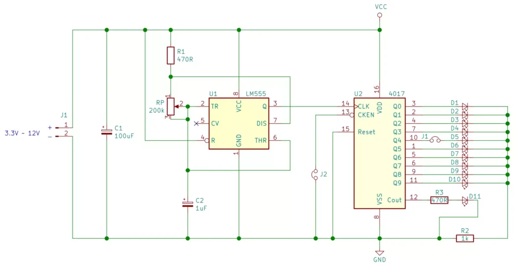
The exact functions of individual resistors and capacitors depend on how they are connected in the kit’s circuit. Use the supplied circuit diagram if you want to trace each component’s electrical role. See the circuit diagram below. If your circuit is different, then get the circuit diagram from the kit vendor’s product page.
555 Project Circuit Board
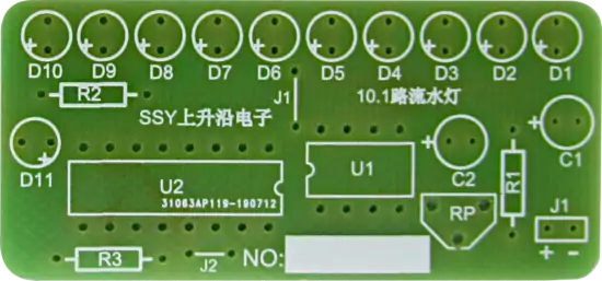
The image of the 555 project circuit board below shows the electronic part reference designators for reference when looking at the table of parts. Reference designators are the U1, U2, R1, R2, R3, J1, etc. markings on the board. They are there so that you know which part to put into which position on the board, and to cross-reference against the circuit diagram. Note that there are two parts marked J1. One is a pin header at the bottom right corner of the image and the other is a jumper link near the middle of the image below.
Tools Required for this 555 Project
You will need a few basic tools to assemble the electronic solder kit.
- Soldering iron with a suitable electronics soldering tip.
- Electronics solder wire.
- Side cutters or wire cutters for trimming component leads.
- Needle-nose pliers or Long-nose pliers for bending resistor leads into jumper links.
- A helping-hands tool or magnifier to hold and inspect the PCB.
- A small flat-blade screwdriver for adjusting the trimmer potentiometer.
- A multimeter for checking resistor values, supply voltage, and electrical connections.
A fume extractor or suitable ventilation is also recommended when soldering. Work in a well-lit area, keep the hot soldering iron in a proper stand, and avoid touching the tip or freshly soldered joints.
How to Power the 555 Project
Before assembling the 555 project kit, decide how you intend to supply power. The board is specified to operate from a DC supply between 3.3 V and 12 V. A 9 V battery is a convenient option for testing, while a regulated 5 V breadboard supply can also be used.
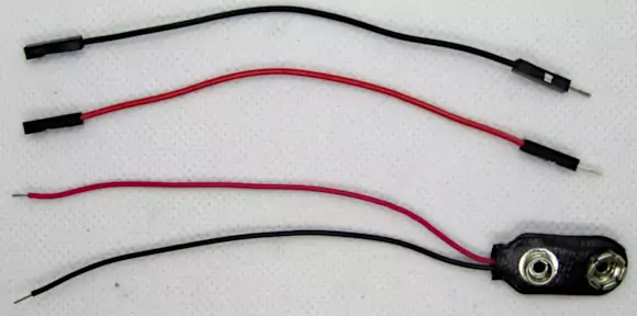
The kit includes a two-pin power connection marked with positive (+) and negative (−) symbols. There are several ways to connect the supply as outlined below. Power is normally connected to the board after soldering the main components, but you need to decide how to power the board first, as there is no battery holder or power supply that comes with the kit. These need to be obtained separately.
Important: Never reverse the power connections. Connecting the supply incorrectly may damage the integrated circuits or other components. Disconnect the power before working on or inspecting the board.
Option 1: Connect a battery clip directly to the PCB
You can solder a 9 V battery clip directly to the power input instead of installing the two-pin header.
- Identify the positive and negative power input holes.
- Insert the red battery clip wire into the hole marked +.
- Insert the black battery clip wire into the hole marked −.
- Solder both wires securely.
- Allow the joints to cool before connecting the battery.
This approach provides a direct connection without separate jumper wires. Check the polarity carefully before soldering because the board does not provide reverse-polarity protection.
Option 2: Use the two-pin header
The kit’s two-pin male header allows you to connect a suitable power cable.
- Solder the header into the rectangular area marked J1.
- Obtain a compatible two-pin female connector or suitable jumper wires.
- Connect the positive supply lead to the + pin.
- Connect the negative supply lead to the − pin.
Some battery holders use a two-pin connector with 2.54 mm spacing. Check the connector pitch before buying one, as connectors with different spacing may not fit.
Option 3: Use a breadboard power supply
A regulated 5 V breadboard power supply is another option. Use suitable Dupont wires to connect the positive and negative outputs to the corresponding power input pins on the PCB.
How to Solder the 555 Project Kit
If you have never soldered before, first learn how to make a reliable solder joint and how to use a soldering iron safely. The 555 project kit is a good practical exercise, but it is easier to assemble if you are already familiar with basic soldering techniques.
Different versions of a 555 project kit may have different component layouts. Always compare the instructions below with the markings on your own PCB. Make the necessary adjustments if your board is different from the one shown.
Step 1: Identify the PCB and component positions
Place the PCB on a flat work surface and identify the reference designators printed on it. These labels indicate where each component belongs.
For example:
- U1 identifies the 555 timer IC.
- U2 identifies the CD4017BE decade counter.
- R1, R2, and R3 identify the resistors.
- D1 to D11 identify the LEDs.
- C1 and C2 identify the capacitors.
- RP identifies the trimmer potentiometer.
The board also has two locations marked J1 for different purposes. The rectangular J1 outline is for the two-pin power header. The other jumper positions are used for wire links. Refer to the PCB markings and circuit diagram to distinguish them.
Step 2: Identify and solder the resistors
Resistors are installed first because they sit close to the PCB and are easier to solder before taller components are added. The kit contains three resistors as the following table shows.
| Reference | Resistance | Five-band color code |
|---|---|---|
| R1 | 470 Ω | Yellow, violet, black, black, brown |
| R2 | 1 kΩ | Brown, black, black, brown, brown |
| R3 | 470 Ω | Yellow, violet, black, black, brown |
Read the color bands carefully. If you are unsure of a resistor’s value, check it with a multimeter set to resistance mode before inserting it.
To install each resistor:
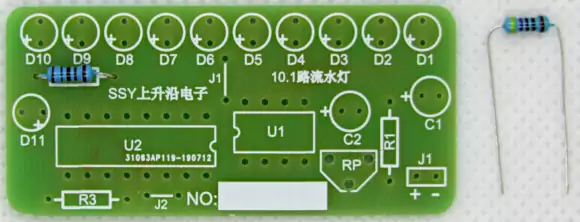
- Bend the leads so that they fit through the appropriate PCB holes as the first image below shows.
- Insert the resistor into its marked position.
- Bend the leads slightly outward on the underside to hold it in place.
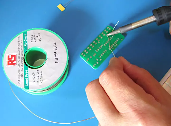
- Turn the PCB over and solder each lead as the second image below shows.
- Allow the solder joints to cool.
- Trim the excess lead length with side cutters.
The resistors are not polarized, so either lead can go into either of the two holes assigned to that resistor.
Inspect each solder joint to ensure that the lead is securely connected to its pad. Avoid applying heat for longer than necessary, and do not allow adjacent solder pads to become bridged.
Step 3: Make and solder the jumper links
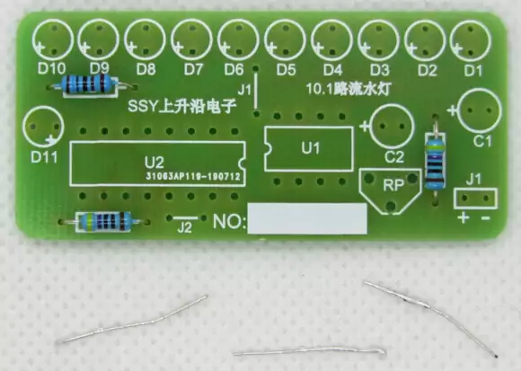
The two jumper links can be made from the spare resistor leads left over from the previous step. These are the excess parts of the resistor leads or legs that were cut off after soldering the resistors. The image below shows these off-cuts that are produced after soldering the resistors.
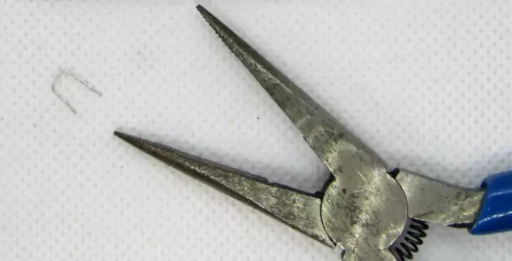
Use long-nose pliers to bend each piece of wire into a shape that fits the jumper holes. Compare the width of the bends with the PCB markings before inserting the links. A newly made jumper link is shown in the image below with the pliers used to bend it.
Insert the links into the positions indicated for the jumpers, not the rectangular power-header position. Bend the leads slightly to keep the links in place, then solder them to the board as the following image shows.
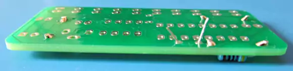
Trim the excess wire after soldering.
These links provide electrical connections required by the kit. Do not omit them or place them in different positions unless the instructions for your particular PCB specify otherwise. Your board should now look like the following image with all the resistors and both the jumper links installed.
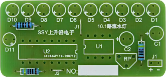
Step 4: Install the NE555P and CD4017BE integrated circuits
The two integrated circuits must be installed with the correct orientation.
The NE555P has eight pins and is installed at U1. The CD4017BE has 16 pins and is installed at U2. Each IC has a notch at one end of its package. The PCB has a corresponding notch marking that indicates the correct direction.
Before inserting an IC, check whether its pins are spread outward as the following image shows.
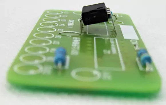
If necessary, gently align the IC pins by resting one row of pins against a flat surface with the IC lying on its left or right side and applying light, even pressure, as the image below shows. Repeat for the row of pins on the other side if required.
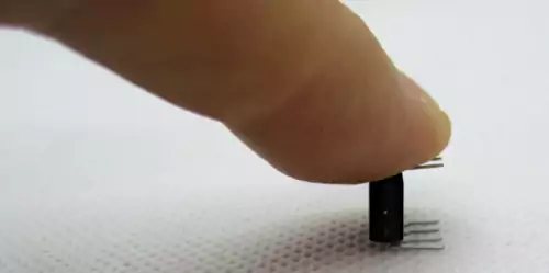
To install each IC:
- Align the pins with the PCB holes.
- Confirm that the notch on the IC matches the notch marking on the board.
- Insert the IC carefully, ensuring that no pins bend underneath the package.
- Turn the board over and solder one pin.
- Check that the IC sits flat and is correctly aligned. If it does not, then push down on the IC while reheating the one pin that was previously soldered, so that the IC snaps into place sitting flat on the board.
- Allow the soldered joint to cool so that the IC is held firmly in place by this joint.
- Solder the remaining pins.
Use a socket if your particular kit provides one or if you choose to use your own IC socket. If the kit is designed for direct soldering, avoid overheating the pins and package. Never force an IC into the PCB if the pins are not aligned with the holes. After completing this step, the board should look like the image below with both ICs soldered in place correctly.
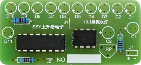
Step 5: Solder the ten main LEDs
The ten main LEDs create the running light effect. Correct LED polarity is essential because LEDs conduct current in one direction. On this kit, the longer LED lead goes into the hole marked with a plus sign (+). The image below shows the longer lead of the LED aligned with the LED outline + marking on circuit board.
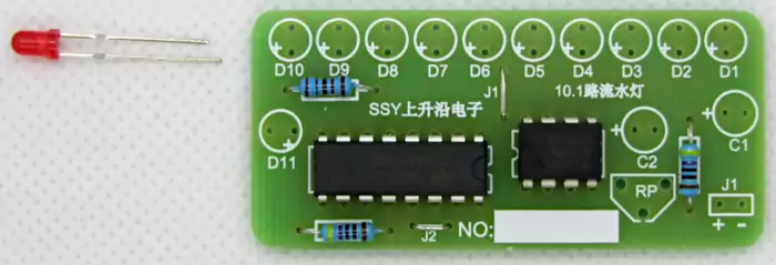
Install LEDs D1 through D10 as follows:
- Identify the positive hole for each LED position.
- Insert the longer lead into the positive hole.
- Check that each LED is seated at the desired height.
- Bend the leads slightly underneath the board to hold the LEDs in place.
- Solder the leads.
- Trim the excess lead length.
You can insert all ten LEDs before soldering as the following image shows, or install and solder them one at a time. Installing them together can help keep the LEDs at a consistent height. Check the polarity of every LED before inserting and soldering. An LED installed backwards will not light, even if the rest of the circuit is working correctly.
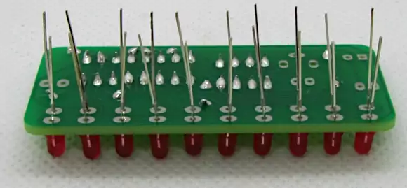
The next image shows a top and bottom view of the PCB with D1 to D10 soldered in place.
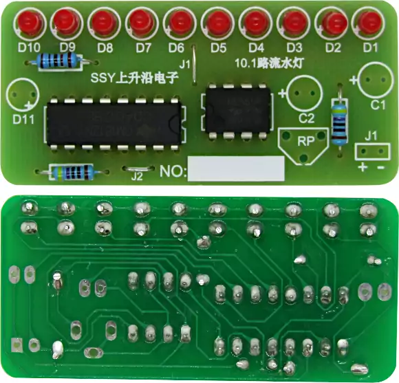
Step 6: Solder the eleventh LED
LED D11 is installed separately from the main ten-LED display. It provides the additional flashing effect that occurs when the main sequence returns to the beginning.
Insert D11 with its longer lead in the hole marked +, then solder both leads and trim the excess wire.
Step 7: Solder the trimmer potentiometer
The 200 kΩ trimmer potentiometer is marked RP on the PCB. It allows you to adjust the timing and change the running light speed.
Insert the three pins into the corresponding holes. Solder one pin first, then check that the trimmer is sitting straight against the board. If it is tilted, reheat that joint carefully while adjusting the component’s position.
Once it is correctly aligned and the solder joint has cooled, solder the remaining two pins.
You will use a small flat-blade screwdriver to adjust the trimmer after powering up the completed circuit.
Step 8: Install the power header or battery clip
If you plan to use the two-pin header, insert it into the rectangular area marked J1 and solder both pins.
Alternatively, solder a battery clip directly to the board. Strip the ends of the wires if necessary, then connect the red wire to the positive (+) hole and the black wire to the negative (−) hole.
Choose one method that suits your intended power connection. Do not install wires or a header in the wrong jumper position.
Step 9: Solder capacitor C2
Capacitor C2 is the 1 µF capacitor specified in the component list.
This capacitor is polarized, so it must be inserted with the correct orientation. The longer lead goes into the hole marked +.
Insert the capacitor into the C2 position, solder both leads, and trim the excess wire.
Step 10: Solder capacitor C1
Capacitor C1 is the 100 µF, 16 V capacitor.
Insert it into the C1 position with the longer lead in the hole marked +. Check the polarity carefully before soldering, then trim the leads once the joints have cooled.
Electrolytic capacitors can be damaged by incorrect polarity. If the capacitor has a stripe marking its negative side, use that marking as an additional check against the PCB’s polarity symbols.
Step 11: Inspect the completed 555 Project PCB
Once all the components have been installed on the 555 project PCB, inspect both sides of the board before applying power.
Check the following:
- All three resistors are in their correct positions.
- The jumper links are installed in the correct holes.
- Both integrated circuits face the correct direction.
- All eleven LEDs have the correct polarity.
- The trimmer potentiometer is securely soldered.
- The power header or battery clip is connected correctly.
- Capacitors C1 and C2 have the correct polarity.
- No solder bridges connect neighboring pads.
- No component leads are touching other leads or unintended parts of the circuit.
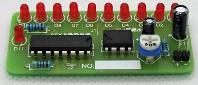
Use a magnifier if necessary. A short inspection now can save time when troubleshooting the completed circuit. The completed circuit is shown in the image below. As can be seen in the image, the pin header option was selected for connecting power to the board.
Testing the Completed 555 Project
After checking the solder joints and component orientations, connect a suitable DC power supply. Start with a voltage within the kit’s specified range and verify the polarity before switching on.
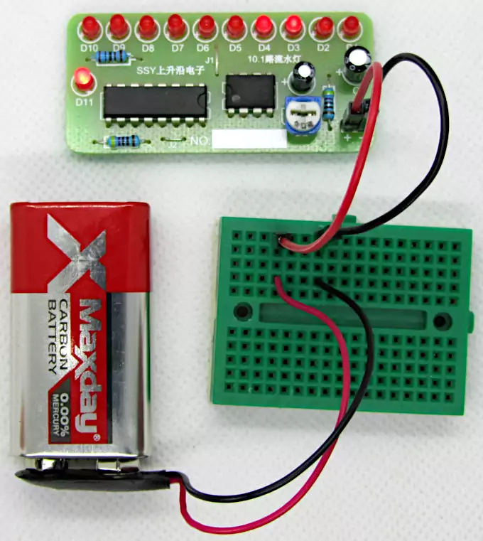
For the example using a 9 V battery, connect the positive lead to + and the negative lead to −. Do not hold a battery against a clip in reverse orientation to test it. This can still apply reverse voltage to the circuit and damage it.
When the circuit is working correctly, the ten main LEDs should light one at a time in sequence. After the tenth LED, the sequence should return to the first LED and repeat. The eleventh LED should also produce its separate flashing effect.
The image below shows a 9V battery connected to the circuit using a small breadboard and DuPont wires.
Adjust the 555 project running light speed
The trimmer potentiometer changes the speed of the display. Use a small flat-blade screwdriver to turn the adjustment gently.
If the LEDs are changing too quickly to distinguish individual steps, slow the circuit down until you can clearly see the sequence. If the display is too slow, adjust the trimmer in the opposite direction.
The direction in which you need to turn the trimmer depends on the particular circuit and its wiring. Make small adjustments and observe the result rather than assuming that clockwise rotation always increases the speed.
Troubleshooting the 555 Project
If the running light does not operate as expected, check the simplest possibilities first. Many faults in beginner soldering projects are caused by incorrect power connections, reversed components, misplaced jumpers, or poor solder joints.
| Problem | Possible cause | What to check |
|---|---|---|
| No LEDs light up | No power reaching the PCB | Measure the supply voltage and check the connection at J1 |
| No LEDs light up | Reversed power polarity | Confirm positive is connected to + and negative to − |
| Some LEDs do not light | Incorrect LED orientation or poor solder joint | Check LED polarity and inspect the solder pads |
| LEDs remain on the same step | Faulty clock signal or counter connection | Inspect U1, U2, the jumpers, and their solder joints |
| LEDs move too quickly | Timing adjustment is unsuitable | Adjust the trimmer potentiometer |
| LEDs move too slowly | Timing adjustment is unsuitable | Adjust the trimmer potentiometer |
| Display behaves erratically | Loose connections, poor joints, or supply problems | Inspect the board and measure the supply voltage |
| Eleventh LED does not flash as expected | Incorrect component installation or a fault in its associated circuitry | Check D11 polarity, component positions, and solder joints |
Check the power supply first
Set a multimeter to an appropriate DC voltage range and measure the supply output. Then check that the voltage reaches the PCB’s power input.
Do not assume that a battery is good simply because it shows a reasonable voltage when measured with a multimeter. A depleted battery may provide insufficient voltage under load.
Inspect the solder joints
Look for joints that are cracked, poorly wetted, or connected to too little solder. Also check for solder bridges between neighboring pads.
If a joint needs rework, disconnect the power first. Allow the soldering iron to heat fully and use it carefully to correct the joint without overheating the PCB.
Check component orientation
Pay particular attention to the integrated circuit notches, LED polarity, and the positive leads of C1 and C2. These are easy mistakes to make during assembly and can prevent the circuit from working.
Adjust the trimmer potentiometer
If the circuit appears to work but the LEDs change too rapidly to see, adjust the trimmer before assuming that a component is faulty. A display that is too fast can appear to be continuously lit or behave differently from what you expect.
Tips for 555 Project Assembly and Testing
These practical tips can make this 555 project easier to assemble and help you avoid common beginner mistakes.
- Sort the components before soldering. Separate the resistors, capacitors, LEDs, and integrated circuits. Confirm each value against the parts list before inserting it.
- Start with the lowest components. Resistors and jumper links are easier to solder before taller components are installed.
- Double-check the IC orientation. Match the notches on the NE555P and CD4017BE with the PCB markings before soldering.
- Check LED polarity individually. The longer lead goes into the positive hole on this kit. Once the leads have been trimmed, other markings on the components must be used to check the correct polarity and orientation.
- Keep the soldering iron tip clean. A clean tip helps transfer heat efficiently and makes it easier to create reliable solder joints.
- Use only enough solder to make a good joint. Excess solder can bridge neighboring pads, especially around the IC pins.
- Use a multimeter before applying power. Check resistor values during assembly and verify the supply voltage and polarity before testing.
- Make small speed adjustments. Turn the trimmer gradually and observe how the display responds.
- Disconnect power before reworking the board. Never solder or change components while the circuit is energized.
- Keep the original circuit diagram nearby. The markings and connections can vary between similar running light kits, so do not assume that all versions use identical layouts.
A well-organized assembly process is often more useful than trying to solder quickly. Taking a little extra time to check each component makes the first power-up more predictable.
About 555 Project Circuits
The 555 timer is one of the most widely recognized integrated circuits in introductory electronics. It can be configured for timing, pulse generation, oscillation, and other functions, making it useful in many different circuits.
Here are a few interesting facts related to this project.
The 555 timer can work without a microcontroller. This running light produces its repeating clock signal using basic timing circuitry. It does not require software, firmware, or programming.
The CD4017BE converts pulses into a visible sequence. A clock pulse advances the counter by one step, so the circuit turns a repetitive electrical signal into a moving display.
The same basic principle has many applications. Sequential LED circuits can be used for indicator displays, educational demonstrations, decorative lighting, and simple visual signals. The precise behavior depends on the circuit design.
A running light is not necessarily a Knight Rider display. Some LED chasers reverse direction at the end of the sequence. This kit instead returns to the first LED after the tenth, so the light travels in one direction only.
The 555 timer and decade counter make a useful learning combination. Together, they demonstrate two important ideas: generating regular pulses and using those pulses to control a sequence of digital outputs.
Frequently Asked Questions About 555 Project Circuits
What is a 555 project?
A 555 project is an electronic circuit or practical build that uses the 555 timer integrated circuit. Projects range from LED flashers and oscillators to alarms and timing circuits. This particular project combines a 555 timer with a CD4017BE counter to operate a running LED display.
What is the CD4017BE used for in this circuit?
The CD4017BE is a decade counter with ten decoded outputs. It advances through its outputs in response to clock pulses from the 555 timer. In this kit, those outputs control the ten main LEDs so that they light in sequence.
Is this a Knight Rider LED display 555 project?
No. A traditional Knight Rider-style display typically moves back and forth along a row of LEDs. This kit lights the ten LEDs in one direction, then returns to the first LED and repeats. The eleventh LED has a separate flashing function.
How many LEDs are included in the running light?
The kit contains eleven red LEDs. Ten LEDs form the main sequential display, while the eleventh LED flashes independently for a period of time when the main sequence returns to its starting point.
What voltage does the 555 project require?
The kit is specified to operate from a DC supply between 3.3 V and 12 V. A 9 V battery is one convenient option, and a regulated 5 V supply is another. Always check the specifications for your particular kit and connect the supply with the correct polarity.
Can I change the speed of the LED chaser?
Yes. The kit includes a 200 kΩ trimmer potentiometer marked RP. Adjusting it changes the timing of the running light, allowing you to make the LED sequence faster or slower.
Why are the LEDs not lighting in sequence?
First, check the power supply, LED polarity, solder joints, IC orientation, and jumper positions. If the display appears to remain on one step, inspect the clock and counter connections. If the display is changing too quickly to see, adjust the trimmer potentiometer before replacing components.
Do I need programming skills to build this kit?
No. The circuit uses the 555 timer and CD4017BE to generate and control the LED sequence without a microcontroller. You only need to assemble the components correctly and connect a suitable power source.
What tools are needed to assemble an electronic solder kit?
At a minimum, you need a soldering iron, electronics solder, and side cutters / miniature wire cutters. Long-nose pliers or needle nose pliers, a magnifier, and a multimeter are also useful. If you are new to electronics, learn basic soldering and component identification before beginning assembly.
Can I modify this circuit to make a different LED display?
Potentially, yes. The 555 timer and CD4017BE can be used in many sequential LED circuits. However, changing the number of LEDs, the direction of the sequence, or the timing behavior may require changes to the circuit connections or components. Consult the circuit diagram before modifying the PCB, and avoid assuming that a modification will work without checking the relevant connections.
Final Thoughts on the 555 Project
This 555 project provides a practical introduction to electronic components, soldering, timing circuits, and decade counters. By assembling the NE555P timer, CD4017BE counter, eleven LEDs, resistors, capacitors, and trimmer potentiometer, you can build a running light that repeatedly steps through ten LEDs while an additional LED flashes independently.
The project also teaches useful skills that apply to many other electronics builds, including reading component markings, recognizing polarity, making reliable solder joints, connecting a DC supply safely, and troubleshooting a completed PCB.
For beginners, this running light electronic solder kit is a useful way to move from learning about individual components to building a working circuit. Once you understand how the 555 timer generates pulses and how the CD4017BE sequences its outputs, you will have a solid foundation for exploring more advanced LED chasers and other timer-based electronics projects.
You may also be interested in our 555 timer circuits article.