
Resistors in series are two or more resistors connected end-to-end in a single electrical path. This is one of the simplest and most important resistor configurations in electronics. Understanding how resistors in series work makes it easier to calculate circuit resistance, understand voltage division, and design practical electronic circuits. In this guide, you will learn how to identify a series connection, calculate the total resistance, determine the voltage across individual resistors, and build a simple series resistor circuit.
What Are Resistors in Series?
Resistors are connected in series when they are joined end-to-end so that the same current must flow through each resistor. There is only one path for current to follow through the series-connected components.
The total resistance of the circuit is equal to the sum of all the individual resistor values.

For example, if three resistors with values of 100Ω, 220Ω, and 330Ω are connected in series as the above image shows, their combined resistance is:
100Ω + 220Ω + 330Ω = 650 Ω
This means that the three resistors behave like a single 650Ω resistor when viewed from the two ends of the combination.
In a series circuit, the following rules apply:
- The same current flows through every resistor.
- The supply voltage is divided across the individual resistors.
- The total resistance is the sum of all resistor values.
- Adding more resistors increases the total resistance.
- If any resistor or connection becomes open circuit, current stops flowing through the entire series path.
These principles apply whether you connect two resistors in series or many resistors together.
How to Calculate the Total Resistance of Resistors in Series
Calculating the total resistance in a series circuit is straightforward. You simply add the resistance values of all the resistors connected in the series path.
This is sometimes called the equivalent resistance in series because the entire resistor combination can be replaced by one resistor with the same overall resistance.
Formula for Series Resistance
The formula for series resistance is:
Where:
- = Total resistance in ohms (Ω)
- = Resistance of the first resistor
- = Resistance of the second resistor
- = Resistance of the third resistor
- = Resistance of the last resistor
The formula works for any number of resistors connected in series.
For example, consider a circuit containing four resistors:
| Resistor | Resistance |
|---|---|
| R1 | 100 Ω |
| R2 | 220 Ω |
| R3 | 470 Ω |
| R4 | 1 kΩ |
To calculate the total resistance, add the four values:
The equivalent resistance of the four resistors is therefore 1.79kΩ.
This means that the entire combination can be replaced by a single 1.79kΩ resistor without changing the overall voltage-current relationship at its terminals.
Example: Calculating the Resistance of Two Resistors in Series
Let’s look at a simpler example using two resistors in series.

Suppose a circuit contains the following resistors in series, as the above image shows:
- R1 = 470Ω
- R2 = 1kΩ
The total resistance is calculated as follows:
The two resistors have an effective series resistance of 1.47kΩ.
You can also use this calculation in reverse. If you need a particular total resistance but do not have a resistor with the exact value, you can combine two or more standard resistor values in series to obtain the required resistance.
For example, a 1.5kΩ resistance can be made using a 1kΩ resistor, a 470Ω, and 30Ω resistor in series, giving 1.5kΩ. Alternatively a 1kΩ resistor and 470Ω resistor in series gives a total of 1.47kΩ, which is close to the desired value and may be suitable for many applications.
Resistors in Series and Current Flow
One of the most important characteristics of resistors in series is that the current is the same through every resistor. This happens because there is only one path for current to flow. The current cannot split between components as it can in a parallel circuit.
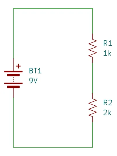
Consider a circuit containing a 9V battery and two resistors connected in series, as shown in the circuit diagram above:
- R1 = 1kΩ
- R2 = 2kΩ
The total resistance is:
Using Ohm’s law, the current flowing through the circuit is:
Therefore:
The current through both resistors is 3mA, or three milliamps.
This is an important difference between series and parallel circuits. In a parallel circuit, the current divides between the available paths. In a series circuit, the same current passes through every component.
Voltage Division in Resistors in Series
Another important characteristic of resistors in series is that the supply voltage is divided across the individual resistors.
The voltage across each resistor depends on its resistance value. A resistor with a higher resistance has a greater voltage drop than one with a lower resistance, provided the same current flows through both.
This principle is known as voltage division and is used in many electronic circuits.
How Voltage Is Divided Across Series Resistors
To calculate the voltage across an individual resistor or combination of resistors in series, use Ohm’s law:
Since the current is the same through every resistor, you can calculate the voltage across each one by multiplying the circuit current by its resistance.
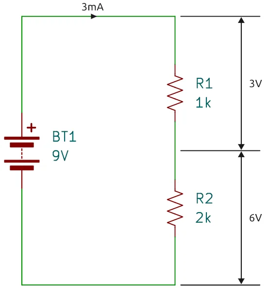
Let’s use the previous example:
- Supply voltage = 9V
- R1 = 1kΩ
- R2 = 2kΩ
- Total resistance = 3kΩ
- Circuit current = 3mA
The voltage across R1 is:
The voltage across R2 is:
The voltage drops add up to the supply voltage:
Notice that the 2kΩ resistor has twice the resistance of the 1kΩ resistor, so it has twice the voltage drop. The following image shows the current flow in the circuit and the voltage drops across the two resistors.
Voltage Divider Formula
You can calculate the voltage across an individual resistor directly using the voltage divider formula:
Where:
- = Voltage across the resistor
- = Total supply voltage
- = Resistance of the resistor
- = Total series resistance
For example, to calculate the voltage across the 2kΩ resistor in the previous circuit:
This formula is particularly useful when designing a voltage dividing circuit.
What Is a Voltage Dividing Circuit?
A voltage dividing circuit, also called a voltage divider, uses two or more resistors connected in series to produce a lower voltage at a point between the resistors.
The output voltage is measured between the junction of the resistors and one end of the supply.
Voltage dividers are commonly used to:
- Provide a lower voltage reference for electronic circuits.
- Adjust signal levels.
- Set the input voltage of certain sensors and measuring circuits.
- Provide a reference voltage for analog inputs.
- Bias transistors and other electronic components.
One important limitation is that connecting a load to the output of a simple voltage divider can change its output voltage. This happens because the load effectively forms a parallel resistance with the lower divider resistor.
For this reason, voltage dividers are generally best suited to applications where the load draws very little current, or where an additional buffer circuit is used.
What Happens When You Add More Resistors in Series?
Adding more resistors in series increases the total resistance of the circuit.
For example, consider a circuit that initially contains two resistors:
- R1 = 100Ω
- R2 = 220Ω
The total resistance is:
Now add a third resistor with a value of 330Ω.
The new total resistance becomes:
The total resistance has increased from 320Ω to 650Ω.
If the supply voltage remains constant, the current flowing through the circuit decreases as the total resistance increases.
This follows directly from Ohm’s law:
For a fixed supply voltage, increasing resistance reduces current.
Can You Connect Different Resistor Values in Series?
Yes. You can connect resistors of different resistance values in series.
There is no requirement for the resistors to have matching values. You can combine resistors of almost any resistance values, provided their power ratings and voltage ratings are suitable for the circuit.
For example, the following combinations are all valid:
| Resistors Connected in Series | Total Resistance |
|---|---|
| 100 Ω + 100 Ω | 200 Ω |
| 220 Ω + 470 Ω | 690 Ω |
| 1 kΩ + 2.2 kΩ | 3.2 kΩ |
| 4.7 kΩ + 10 kΩ | 14.7 kΩ |
| 10 kΩ + 10 kΩ + 10 kΩ | 30 kΩ |
This flexibility makes series resistor combinations useful when a specific resistance value is required but an individual resistor with that value is unavailable.
How to Connect Breadboard Resistors in Series
A solderless breadboard makes it easy to experiment with resistors in series without soldering.
You can use a breadboard to build a simple circuit, measure its resistance, and investigate how voltage is divided between the resistors.
Components Required
For this experiment, you will need:
- One solderless breadboard.
- One 1kΩ resistor.
- One 2.2kΩ resistor.
- A digital multimeter.
- A 9V battery or suitable low-voltage DC power supply.
- Jumper wires.
Building the Series Resistor Circuit
Important: Make sure the power supply is disconnected while building or changing the circuit.
Follow these steps to connect the breadboard resistors in series:
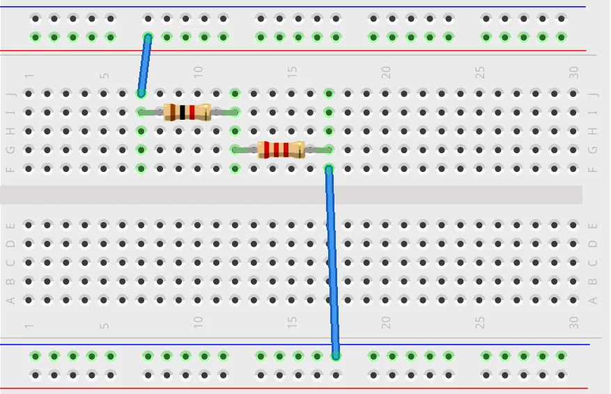
- Insert the first resistor (1kΩ) into the breadboard, placing its two leads in separate connected terminal strips.
- Insert the second resistor (2.2kΩ) so that one of its leads shares the same connected terminal strip as one lead of the first resistor.
- The two resistors are now connected in series.
- Use jumper wires to connect the free end of the first resistor to the positive supply terminal.
- Connect the free end of the second resistor to the negative supply terminal.
The completed circuit shown below has a single current path through both resistors.
Measuring the Total Resistance
Before connecting the power supply, you can use a multimeter to measure the total resistance of the two resistors.
- Set the multimeter to resistance mode (Ω).
- Make sure the power supply is disconnected from the circuit.
- Place one multimeter probe at the free end of the first resistor.
- Place the other probe at the free end of the second resistor.
- Read the resistance displayed on the multimeter.
The expected resistance is:
The measured value may differ slightly because resistors have a specified tolerance. For example, a resistor with a tolerance of ±5% can have an actual resistance that is up to 5% higher or lower than its marked nominal value.
Measuring the Voltage Across Each Resistor
You can also investigate voltage division by measuring the voltage across each resistor while the circuit is powered. Select DC voltage (V DC) measurement on the multimeter before measuring voltage on across the resistors. With a 9V supply and the two resistors connected in series, the total resistance is 3.2kΩ.
When measuring voltage, connect the multimeter probes across the resistor being measured. Do not place the multimeter in current mode across the supply or directly across a resistor. Also be sure that DC voltage is selected rather than resistance that we used previously.
The circuit current is:
The voltage across the 1kΩ resistor is:
The voltage across the 2.2kΩ resistor is:
The two voltage drops add up to approximately 9V. Remember that a fully charged 9V battery will have a voltage slightly above 9V. If the battery is discharged by some amount, then its voltage could be near to or slightly below 9V. This slight voltage difference and the tolerance of the resistors means that the voltages measured across the resistors will never be exactly as calculated, but somewhere close to the calculated values.
To calculate the voltage drop across each resistor more accurately, start by disconnecting the battery from the circuit. Put the multimeter onto the resistance or ohms scale. Measure the resistance of the first resistor and write it down, and then do the same for the second resistor. Finally, select DC voltage measurement on the multimeter and measure the battery voltage when it is connected to the circuit. Record the measured voltage. Now use the measured resistor values and measured voltage value in the above calculations.
This simple experiment demonstrates how resistors in series divide voltage according to their resistance values.
Resistors in Series vs. Resistors in Parallel
Series and parallel connections are two basic ways of connecting resistors in an electronic circuit. Although both arrangements combine individual resistance values, their calculations and behavior are different.
The following table compares the two configurations.
| Feature | Series Connection | Parallel Connection |
|---|---|---|
| Current | Same through every resistor | Divides between branches |
| Voltage | Divided across resistors | Same across every branch |
| Total resistance | Sum of individual resistances | Less than the smallest branch resistance |
| Adding resistors | Increases total resistance | Decreases total resistance |
| Current paths | One | Multiple |
Series Resistance Formula
For resistors in series:
Parallel Resistance Formula
For resistors in parallel:
For two resistors in parallel, you can use the simpler formula:
Remember that the series formula involves adding resistance values directly, while the parallel formula involves adding their reciprocals.
For more information about parallel resistor connections, see our guide to resistors in parallel.
Power Dissipation for Resistors in Series
When current flows through a resistor, electrical energy is converted into heat. This is known as power dissipation. Each resistor in a series circuit dissipates power according to its resistance and the current flowing through it.
The power formula is:
Where:
- = Power in watts (W)
- = Current in amperes (A)
- = Resistance in ohms (Ω)
Let’s use a circuit with a 9V supply and two resistors:
- R1 = 1kΩ
- R2 = 2kΩ
- Circuit current = 3mA
The power dissipated by R1 is:
The power dissipated by R2 is:
The 2kΩ resistor dissipates twice as much power because it has twice the resistance and carries the same current.
Choosing the Correct Resistor Power Rating
When designing a circuit, make sure each resistor has a suitable power rating.
Common resistor power ratings include:
- 0.125 W (⅛ watt)
- 0.25 W (¼ watt)
- 0.5 W (½ watt)
- 1 W
- 2 W
A resistor should not normally be operated continuously at its maximum rated power without considering the manufacturer’s derating recommendations and the operating temperature.
For many beginner circuits, standard 0.25W resistors are sufficient, but always calculate the expected resistor power dissipation before selecting components.
Practical Applications of Resistors in Series
Series resistor connections are used in many different types of electronic circuits.
Understanding these applications helps explain why this simple arrangement is so useful.
Current Limiting
One common application is limiting current.
For example, a resistor connected in series with an LED limits the current flowing through the LED and protects it from excessive current.
The resistor value can be calculated using:
Where:
- = Required resistor value
- = Supply voltage
- = LED forward voltage
- = Desired LED current
For example, suppose you want to connect a red LED with a forward voltage of 2V to a 9V supply. If the desired current is 10mA:
A standard 680Ω or 750Ω resistor could be considered, depending on the desired current and LED specifications.
Voltage Dividers
As discussed earlier, two or more series resistors can be used to produce a lower output voltage from a higher supply voltage. This is known as a voltage divider circuit.
This is useful when a circuit needs a particular reference voltage or a reduced signal level.
Increasing Resistance
Sometimes a circuit requires a resistance value that is not readily available as a single standard resistor.
Connecting two or more resistors in series provides a simple way to obtain a higher combined resistance.
For example, two 4.7kΩ resistors in series produce:
Resistor Networks
Multiple resistors connected in series are also used as part of larger resistor networks.
These networks can provide voltage references, distribute voltage across different circuit sections, and help establish operating conditions for electronic components.
Tips for Resistors in Series
The following tips will help you work with series resistor combinations more effectively.
- Always add the resistance values: The total resistance of a series combination is the sum of all individual resistor values.
- Check the resistor values: Use the resistor color code or a multimeter to verify component values before building a circuit.
- Remember that current is the same: The current through every resistor in a series path is identical.
- Use the voltage divider formula: This makes it quicker to calculate the voltage across individual resistors without first calculating the circuit current.
- Check resistor power ratings: Calculate the expected power dissipation to avoid overheating or damaging components.
- Use standard resistor combinations: If you do not have the exact resistance required, consider combining standard resistor values in series.
- Measure resistance with the power off: Never use the resistance setting on a multimeter when the circuit is powered.
- Check breadboard connections: Make sure the resistor leads are inserted into the correct connected terminal strips.
- Consider resistor tolerance: The actual resistance may differ slightly from the nominal value printed on the component or indicated by its color bands.
Did You Know?
Resistors in series have several interesting properties and uses that are worth knowing.
You Can Create Resistance Values That Are Not Standard
Resistors are manufactured in standard preferred value ranges. However, you are not limited to using only the available individual values. By connecting resistors in series, you can create additional resistance values.
For example, a 1kΩ resistor and a 330Ω resistor connected in series produce a combined resistance of 1.33kΩ.
This is useful when designing circuits that require a resistance value that is not readily available.
Series Resistors Can Be Used to Share Voltage
A series resistor chain can divide a high voltage into smaller voltage drops. This principle is used in voltage divider circuits and certain resistor networks.
However, the resistors must have suitable individual voltage ratings. The total voltage rating of a resistor chain should not automatically be assumed to equal the sum of the individual ratings because voltage distribution, resistor construction, and environmental conditions also matter.
The Order of Resistors Does Not Change Their Total Resistance
You can rearrange resistors in a series circuit without changing the total resistance.
For example:
The following arrangement produces exactly the same total resistance:
The order of the resistors does not affect their combined resistance.
However, the voltage measured at intermediate connection points will depend on which resistor is positioned where in relation to the supply and ground.
A Series Circuit Can Have Only One Current Path
Even if a circuit contains many components, it is still a series circuit as long as there is only one path for current through those components.
This is why opening one connection in a simple series circuit stops current everywhere in that path.
Frequently Asked Questions
What Happens When Resistors Are Connected in Series?
When resistors are connected in series, the same current flows through every resistor. The supply voltage is divided across the resistors, and the total resistance is equal to the sum of their individual resistance values.
How Do You Calculate the Total Resistance of Resistors in Series?
Add the resistance values of all the resistors.
For example, if you connect a 100Ω, a 220Ω, and a 330Ω resistor in series:
The total resistance is 650Ω.
Does Current Stay the Same Through Resistors in Series?
Yes. The current is the same through every resistor in a series circuit because there is only one path for current to flow.
If 5mA flows through the first resistor, 5mA also flows through every other resistor in that series path.
Does Voltage Divide Equally Across Resistors in Series?
No. The voltage does not necessarily divide equally.
The voltage drop across each resistor depends on its resistance value. A resistor with twice the resistance of another resistor will have twice the voltage drop, provided both carry the same current.
Voltage divides equally only when the resistors have equal resistance values.
Can You Connect Two Resistors in Series With Different Values?
Yes. Resistors with different resistance values can be connected in series.
For example, a 1kΩ resistor and a 2.2kΩ resistor produce a total resistance of 3.2kΩ.
There is no requirement for series-connected resistors to have the same resistance value.
Does Adding More Resistors in Series Increase Resistance?
Yes. Every additional resistor increases the total resistance by its own resistance value.
For example, adding a 470Ω resistor to an existing series combination increases the total resistance by 470Ω.
What Is the Difference Between Series and Parallel Resistors?
In a series connection, resistors are connected end-to-end in a single current path. The same current flows through every resistor, and their resistance values add together.
In a parallel connection, resistors are connected across the same two electrical points. They have the same voltage across them, while the current divides between the branches.
The total resistance of a parallel combination is lower than the resistance of its smallest individual resistor.
Can Resistors in Series Be Connected on a Breadboard?
Yes. A solderless breadboard is an easy way to connect resistors in series.
Simply insert the leads so that one lead of the first resistor shares an electrically connected terminal strip with one lead of the second resistor. The two remaining leads become the ends of the series combination.
Always check the breadboard’s internal connection layout to ensure the components are connected correctly.
What Is the Equivalent Resistance of Two Resistors in Series?
The equivalent resistance is the sum of the two individual resistance values.
For example, two resistors with values of 470Ω and 1kΩ have an equivalent resistance of:
The two resistors can therefore be replaced by a single 1.47kΩ resistor for calculations involving the overall circuit resistance.
Can Resistors in Series Have Different Power Ratings?
Yes. Series-connected resistors can have different power ratings.
However, each resistor must have a power rating suitable for the amount of power it dissipates in the circuit. A resistor with a lower power rating may overheat even if the other resistors have much higher ratings.
Conclusion
Resistors in series are one of the fundamental building blocks of electronic circuits. By connecting resistors end-to-end, you create a single current path in which the same current flows through every resistor. The total resistance is simply the sum of the individual resistance values.
Understanding the formula for series resistance also makes it easier to calculate circuit current, determine voltage drops, and design voltage divider circuits. Whether you are building a simple LED circuit, experimenting with breadboard resistors in series, or designing a more complex electronic project, knowing how series resistor combinations work is an essential electronics skill.
You may also be interested in how to understand voltage, current and resistance in electronics.