
The 1N4007 diode is a popular general-purpose rectifier diode used in power supplies, electronic circuits, reverse-polarity protection and many other applications. It belongs to the 1N400x family of silicon rectifier diodes and is capable of handling an average forward current of 1A and a maximum repetitive reverse voltage of 1000V.
The 1N4007 diode is inexpensive, readily available and easy to use, making it a common choice for hobby electronics projects and commercial electronic equipment. It is particularly useful for converting AC into DC and protecting circuits against unwanted current flow.
In this guide, we look at the 1N4007 diode pinout, electrical specifications, operating characteristics and common applications. We also compare it with other diodes in the 1N400x series and look at the surface-mount versions available for PCB designs.
What Is a 1N4007 Diode?
The 1N4007 is a general-purpose silicon rectifier diode designed primarily for converting alternating current (AC) into direct current (DC). It allows current to flow in one direction while blocking current in the opposite direction. This makes it useful in circuits where current direction needs to be controlled.
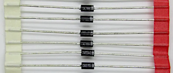
A pack of 1N4007 diodes is shown in the image below taped together. Individual diodes can be cut from the tape when needed.
Some common applications of these diodes include:
- AC-to-DC power supply rectifiers.
- Reverse-polarity protection circuits.
- Flyback protection for relays and other inductive loads.
- Battery charging circuits.
- DC voltage protection.
- General-purpose electronic circuits.
The 1N4007 diode has an average forward current rating of 1A and a maximum repetitive peak reverse voltage rating of 1000V.
It is normally supplied in a DO-41 axial-lead package, with a cylindrical body and a lead extending from each end. A colored band around one end identifies the cathode terminal. The colored band is at the right on each diode in the above image. It is a silver or light gray color.
Although the 1N4007 is designed for relatively low-frequency rectification, it can be used in many everyday electronic circuits where high-speed switching is not required.
1N4007 Diode Pinout and Polarity
The 1N4007 diode has two terminals:
- Anode: The positive-side terminal through which conventional current enters the diode when it is forward biased.
- Cathode: The negative-side terminal through which conventional current leaves the diode when it is forward biased.
The cathode is identified by a silver or white band printed around one end of the diode body. The band is an important feature because it makes identifying the diode’s polarity straightforward when installing it in a circuit.
How to Identify 1N4007 Diode Polarity
Use the following identification guide and the image below to identify the polarity of a 1N4007. The image includes a diode schematic symbol for reference.
| Physical Feature | Terminal |
|---|---|
| End with colored band | Cathode (K) |
| End without colored band | Anode (A) |

When connecting the diode in a circuit:
- For forward bias, connect the anode towards the positive supply and the cathode towards the negative supply.
- For reverse bias, connect the cathode towards the positive supply and the anode towards the negative supply.
When forward biased, the diode conducts once the applied voltage is sufficient to overcome its forward voltage drop. When reverse biased, it blocks current flow, provided the reverse voltage does not exceed its rated limit.
Important: Always check the cathode band before soldering a 1N4007 diode into a PCB or breadboard circuit. Installing it backwards can prevent the circuit from operating correctly.
The following images show the diode forward biased in the first image, causing it to conduct current in the circuit. It is reverse biased in the second image which stops current flow in the circuit.


1N4007 Diode Specifications
Understanding the electrical ratings is important when selecting a diode for an electronic project. The 1N4007 diode is rated for relatively high reverse voltages and moderate forward currents. However, its current rating depends on operating temperature, cooling and mounting conditions.
The following table shows typical specifications found in commonly available 1N4007 datasheets.
1N4007 Diode Specs Table
| Parameter | Symbol | Typical rating or specification |
|---|---|---|
| Maximum repetitive peak reverse voltage | VRRM | 1000 V |
| Maximum RMS reverse voltage | VRMS | 700 V |
| Maximum DC blocking voltage | VDC | 1000 V |
| Average rectified forward current | IF(AV) | 1 A |
| Peak forward surge current | IFSM | 30 A |
| Maximum forward voltage at 1 A | VF | 1.1 V |
| Maximum reverse current at 25°C | IR | 10 µA |
| Typical junction capacitance | CJ | 15 pF |
| Typical reverse recovery time | trr | 1.5 to 2 µs |
| Operating junction temperature | TJ | Depends on manufacturer, commonly up to 150°C or 175°C |
Specifications are representative of common manufacturer versions. Always check the datasheet for the exact part being used.
Let’s look at some of the more important specifications in greater detail.
Maximum Reverse Voltage: 1000V
The 1N4007 has a maximum repetitive peak reverse voltage rating of 1000V. This means that it can withstand a repetitive reverse voltage of up to 1000V under the specified datasheet operating conditions.
The maximum RMS reverse voltage is typically specified as 700V.
These ratings make the 1N4007 suitable for rectifier circuits operating from relatively high AC voltages. However, the reverse voltage rating should not be confused with the voltage that the diode can continuously supply to a load. The diode’s forward current and thermal limitations must also be considered.
Average Forward Current: 1A
The maximum average rectified forward current is typically rated at 1A. This is the average current that the diode can conduct under the conditions specified in its datasheet.
The actual allowable current depends on factors such as:
- Ambient temperature.
- Lead length and PCB mounting.
- Heat dissipation.
- Current waveform.
- Whether the load is resistive or capacitive.
A diode carrying a continuous current close to its maximum rating can become hot. Adequate thermal design is therefore important.
Forward Voltage Drop: 1.1V
When forward biased, the 1N4007 diode develops a voltage drop across its terminals. A commonly specified maximum forward voltage is 1.1V at a forward current of 1A.
For example, if a 1N4007 diode carries 1A, approximately 1.1V will be dropped across it.
The power dissipated by the diode can be estimated using:
At 1A and a forward voltage drop of 1.1V the power is as follows:
This heat must be considered when designing circuits that operate at relatively high currents. At lower currents, the forward voltage drop will generally be lower.
Peak Forward Surge Current: 30A
The 1N4007 can withstand a short-duration forward current surge of approximately 30A. This rating is usually specified for a single 8.3ms half-sine-wave surge, superimposed on the rated load. It is important to understand that this does not mean the diode can continuously carry 30A.
The surge rating is intended to cover brief current spikes, such as those that can occur when a power supply is first switched on and its capacitors begin charging.
Reverse Leakage Current
When reverse biased, a small amount of current can still flow through the diode. This is called reverse leakage current.
For many common 1N4007 versions, the maximum reverse leakage current is specified as 5µA or 10µA at 25°C under the rated reverse voltage.
Reverse leakage generally increases as the diode temperature rises. This characteristic is worth considering in circuits where very low standby current is important.
1N4007 Datasheet
The 1N4007 datasheet provides detailed electrical and mechanical information about the diode. It is the best reference when designing a circuit because different manufacturers can have slightly different specifications, even when producing components with the same part number.
A typical datasheet includes:
- Maximum repetitive reverse voltage.
- Maximum average forward current.
- Peak forward surge current.
- Forward voltage characteristics.
- Reverse leakage current.
- Junction capacitance.
- Reverse recovery time.
- Operating temperature range.
- Package dimensions.
- Electrical characteristics and performance graphs.
You can find manufacturer datasheets for the 1N4007 from semiconductor suppliers. Below are some examples of 1N4007 manufacturers. Each link is to the manufacturer’s 1N4007 web page, where a link to the datasheet is available. Web pages and datasheets may cover the whole 1N4001 to 1N4007 part range.
- Vishay 1N4001, 1N4002, 1N4003, 1N4004, 1N4005, 1N4006, 1N4007
- onsemi 1N4007
- Taiwan Semiconductor 1N4007G
- Diotec Semiconductor 1N4007
When using a datasheet, pay particular attention to the maximum ratings and the test conditions associated with each specification. A maximum rating is not necessarily a recommended continuous operating value for every application.
The 1N4001 to 1N4007 Diode Series
The 1N4007 belongs to a family of general-purpose rectifier diodes known as the 1N400x series. This family contains seven commonly available diode types:
- 1N4001
- 1N4002
- 1N4003
- 1N4004
- 1N4005
- 1N4006
- 1N4007
All seven are designed for general-purpose rectification and have a typical average forward current rating of 1A. The main difference between them is their maximum reverse voltage rating.
1N4001 to 1N4007 Diode Voltage Ratings
As the table below shows, the higher the number after 1N400, the higher the reverse voltage rating. The 1N4001 has the lowest voltage rating, while the 1N4007 has the highest.
| Diode | Maximum repetitive peak reverse voltage |
|---|---|
| 1N4001 | 50 V |
| 1N4002 | 100 V |
| 1N4003 | 200 V |
| 1N4004 | 400 V |
| 1N4005 | 600 V |
| 1N4006 | 800 V |
| 1N4007 | 1000 V |
Which 1N400x Diode Should You Use?
The choice depends mainly on the maximum reverse voltage that the diode will experience.
For example:
- Use a 1N4001 in a low-voltage circuit where a 50V reverse voltage rating is sufficient.
- Use a 1N4004 where a 400V reverse voltage rating is required.
- Use a 1N4007 where a higher reverse voltage rating is needed, up to 1000V.
The 1N4007 is often a convenient choice because it has the highest voltage rating in the series. It can generally replace lower-voltage members of the same series in applications where the other electrical and mechanical characteristics are suitable.
However, a lower-rated diode should never be substituted for a 1N4007 if the circuit can expose it to a reverse voltage greater than its rating.
Common Applications of the 1N4007 Diode
The 1N4007 is used in many electronic circuits because of its simple operation, low cost and relatively high reverse voltage rating. Some common applications follow below.
1. AC-to-DC Rectifier Circuits
One of the most common applications of the 1N4007 is converting AC into DC. A diode allows current to flow during one half of an AC cycle while blocking it during the opposite half. This is called half-wave rectification.
A single 1N4007 can be used in a half-wave rectifier circuit. For full-wave rectification, four diodes can be connected in a bridge configuration.
In a bridge rectifier, two diodes conduct during each half-cycle of the AC supply. This produces a full-wave rectified output. A smoothing capacitor can then be added across the DC output to reduce voltage ripple.
The 1N4007 is commonly used in small power supply circuits, although its current and thermal ratings must be checked for the intended application.
Mains safety: A bridge rectifier built with 1N4007 diodes does not provide electrical isolation. Never connect a beginner breadboard circuit directly to mains electricity. Use an appropriately isolated, certified low-voltage AC supply for experiments.
2. Reverse-Polarity Protection
The 1N4007 can also be used to protect electronic circuits against accidental reverse-polarity connections. For example, consider a circuit powered by a DC battery. If the battery is accidentally connected backwards, the diode can prevent current from flowing through the circuit in the wrong direction.
The diode is connected in series with the positive supply line. When the battery is connected correctly, the diode conducts and supplies power to the circuit. When the battery is connected backwards, the diode becomes reverse biased and blocks current.
The disadvantage of this arrangement is that the diode introduces a forward voltage drop. This reduces the voltage available to the circuit and causes some power to be dissipated as heat.
For applications where this voltage loss is undesirable, a MOSFET-based reverse-polarity protection circuit may be a better solution.
3. Flyback Protection for Relays
The 1N4007 is commonly used as a flyback diode to protect electronic components when switching inductive loads. A relay coil is an example of an inductive load. When current flows through a relay coil, energy is stored in its magnetic field. When the coil is switched off, the magnetic field collapses and can generate a large voltage spike. This voltage spike can damage the transistor or other switching component controlling the relay.
A 1N4007 flyback diode provides a path for the coil current to circulate after the supply is switched off. The diode is connected directly across the relay coil, with its cathode connected to the positive supply and its anode connected to the transistor side of the coil. During normal operation, the diode is reverse biased and does not conduct. When the transistor switches off, the coil generates a reverse voltage that forward biases the diode. The stored energy can then dissipate through the coil and diode. This helps protect the switching transistor from damaging voltage spikes.
The 1N4007 is suitable for many ordinary relay applications. However, it is not ideal for every inductive switching application. Its relatively slow reverse recovery makes it less suitable for high-frequency switching circuits. For faster switching applications, a faster recovery or appropriately selected Schottky diode may be more suitable.
4. Battery Charging Circuits
A 1N4007 can be used in simple battery charging circuits to prevent reverse current. For example, a diode connected between a charging supply and a battery can prevent the battery from discharging back into the supply when the supply is switched off. However, a diode alone does not provide proper battery charging control.
A suitable charging circuit must regulate the charging voltage and current according to the battery chemistry and manufacturer’s requirements.
5. General DC Protection
The 1N4007 can be used in some DC protection circuits to block unwanted current paths. Examples include:
- Preventing reverse current between two power supplies.
- Protecting circuit sections against incorrect supply polarity.
- Blocking unwanted current flow in simple switching circuits.
- Isolating different DC supply paths.
The diode’s current rating and forward voltage drop should always be considered when using it in these applications.
1N4007 Surface-Mount Versions
The standard 1N4007 diode is supplied in an axial-lead package, commonly known as DO-41. This package is designed for through-hole mounting, where the leads pass through holes in the PCB and are soldered on the opposite side. However, surface-mount versions of the 1N4007 are also available.
These are useful for modern PCB designs where components are mounted directly onto the copper pads rather than inserted through holes.
M7 Surface-Mount Diode
One common surface-mount version is the M7 diode. The M7 is a surface-mount general-purpose rectifier with specifications similar to the standard 1N4007. A typical M7 version has:
| Parameter | Typical Specification |
|---|---|
| Maximum repetitive peak reverse voltage | 1000 V |
| Average forward current | 1 A |
| Peak forward surge current | 30 A |
| Maximum forward voltage at 1 A | 1.1 V |
| Package | SMA (DO-214AC) |
The M7 is commonly used as a surface-mount alternative to the through-hole 1N4007. However, it is important to check the manufacturer’s datasheet because package dimensions, thermal characteristics and electrical specifications can vary.
Other Surface-Mount Versions
Other surface-mount rectifiers are also available with similar electrical ratings.
For example:
- S1M: A common 1A, 1000V surface-mount rectifier, generally supplied in an SMA package. For example the S1M from Vishay.
- M7: A surface-mount rectifier commonly rated at 1A and 1000V.
These devices are often considered when designing a PCB that would otherwise use a 1N4007. Although their electrical ratings may be similar, they do not necessarily share identical package dimensions or specifications. Always check the datasheet before using one as a direct replacement.
Choosing Between Through-Hole and Surface-Mount Versions
The choice depends mainly on the PCB design and assembly method.
| Feature | Standard 1N4007 | Surface-mount M7 |
|---|---|---|
| Mounting type | Through-hole | Surface-mount |
| Typical package | DO-41 | SMA |
| Leads | Axial leads | Flat solder terminals |
| PCB installation | Inserted through holes | Soldered onto PCB pads |
| Typical forward current | 1 A | 1 A |
| Typical reverse voltage | 1000 V | 1000 V |
For breadboard experiments and beginner electronics projects, the standard through-hole 1N4007 is usually more convenient. For compact PCB designs and automated assembly, the surface-mount version may be more appropriate.
Is the 1N4007 Suitable for High-Speed Switching?
The 1N4007 is a standard-recovery rectifier diode. It is designed primarily for relatively low-frequency applications, such as 50Hz and 60Hz AC rectification. It has a reverse recovery time typically in the region of 1.5 to 2µs, depending on the manufacturer. Reverse recovery time is the time a diode takes to stop conducting after the voltage across it changes from forward bias to reverse bias.
This characteristic becomes important in high-frequency switching circuits. For example, the 1N4007 is generally not a good choice for:
- High-frequency switching power supplies.
- Fast PWM switching circuits.
- High-speed pulse circuits.
- High-frequency DC-DC converters.
In these applications, a fast-recovery diode or Schottky diode is often more appropriate. However, for ordinary 50Hz or 60Hz rectification and many low-frequency relay protection applications, the 1N4007 remains a practical choice.
How to Test a 1N4007 Diode with a Multimeter
A digital multimeter with a diode test function can be used to check whether a 1N4007 is working correctly. This test checks whether the diode conducts in one direction and blocks current in the other.
Follow these steps:
- Set the digital multimeter to diode test mode.
- Connect the red multimeter probe to the anode of the 1N4007.
- Connect the black probe to the cathode, identified by the colored band.
- Read the voltage displayed on the multimeter.
- Reverse the probes and repeat the measurement.
Expected Multimeter Readings
The following table shows the expected readings on a multimeter when doing a diode test.
| Test Connection | Expected Result |
|---|---|
| Red probe to anode, black to cathode | Approximately 0.5 V to 0.8 V |
| Red probe to cathode, black to anode | OL or open circuit |
The exact forward voltage reading depends on the multimeter’s test current and the diode itself. If the multimeter shows a low voltage in both directions, the diode may be short-circuited. If it shows OL in both directions, the diode may be open-circuit.
For a more reliable test, remove at least one lead from the circuit before testing. Other components connected across the diode can affect the readings.
Tips for the 1N4007 Diode
Here are some practical tips for using the 1N4007 in electronic circuits.
1. Check the cathode band before installation.
The band identifies the cathode. Always check its orientation against the circuit diagram before soldering the diode into place.
2. Do not exceed the current rating.
The 1 A rating is a maximum average forward current under specified conditions, not a guarantee that the diode can carry 1 A in every circuit or environment.
3. Allow for the forward voltage drop.
A forward voltage drop of approximately 1.1 V at 1 A can be significant in low-voltage circuits. Consider this when calculating the voltage available to the load.
4. Use the correct diode for high-frequency applications.
The 1N4007 is a standard-recovery diode. Choose a faster diode if your circuit operates at high switching frequencies.
5. Use a flyback diode with DC relay coils.
Connect the diode across the relay coil, with its cathode towards the positive supply. This helps protect the transistor or switching device.
6. Check the datasheet for your specific manufacturer.
Although different manufacturers produce 1N4007 diodes, their detailed specifications and operating conditions may differ.
7. Consider the PCB mounting arrangement.
The standard DO-41 version is convenient for through-hole projects, while the M7 SMA version is suitable for surface-mount PCB designs.
Did You Know?
The 1N4007 is one of the most widely used general-purpose rectifier diodes in electronics. Here are some interesting facts about this component.
1. The 1N4007 belongs to a family of seven diodes.
The 1N4001 through 1N4007 share similar general-purpose rectifier characteristics. Their main difference is the maximum reverse voltage rating.
2. The 1N4007 can replace many lower-rated 1N400x diodes.
Because it has a 1000 V reverse voltage rating, it can often be used in place of a 1N4001, 1N4002 or other lower-rated member of the series, provided the remaining requirements are compatible.
3. The cathode band is a simple but important feature.
The colored band makes it easy to identify the cathode without needing to consult the component datasheet.
4. The 1N4007 is also used as a relay protection diode.
Although it is primarily a rectifier, its ability to provide a path for current from an inductive load makes it useful as a flyback diode.
5. Surface-mount alternatives are available.
The M7 is an example of a surface-mount rectifier with similar voltage and current ratings to the traditional 1N4007.
6. A higher voltage rating does not mean a higher current rating.
The 1N4007 has a higher reverse voltage rating than the 1N4001, but both typically have the same 1 A average forward current rating.
Frequently Asked Questions
What Is a 1N4007 Diode Used For?
The 1N4007 is a general-purpose rectifier diode used for converting AC to DC, reverse-polarity protection, flyback protection and other applications where current needs to flow in one direction.
Its 1A average forward current and 1000V reverse voltage ratings make it suitable for many low-frequency power supply and protection circuits.
What Is the Maximum Voltage of a 1N4007 Diode?
The maximum repetitive peak reverse voltage of a 1N4007 is 1000V. Its maximum RMS reverse voltage is typically 700V. The diode should not be operated beyond these ratings.
What Is the Maximum Current of a 1N4007?
The 1N4007 typically has a maximum average rectified forward current rating of 1A. It can also withstand a short-duration forward surge current of approximately 30A under the specified test conditions. The 30A surge rating is not a continuous operating current.
What Is the Difference Between 1N4001 and 1N4007?
The main difference is their reverse voltage rating. The 1N4001 has a maximum repetitive peak reverse voltage rating of 50V, while the 1N4007 is rated at 1000V. Both typically have an average forward current rating of 1A.
Can I Use a 1N4007 Instead of a 1N4001?
Yes. A 1N4007 can generally replace a 1N4001 in circuits where the lower-rated diode would normally be used. The 1N4007 has a much higher reverse voltage rating, while retaining similar general-purpose rectifier characteristics. However, always check the other electrical specifications and package requirements.
Can a 1N4007 Be Used as a Flyback Diode?
Yes. The 1N4007 is commonly used as a flyback diode across DC relay coils and other inductive loads. It provides a path for the current generated when the magnetic field collapses after the coil is switched off. For high-frequency switching applications, a faster diode may be a better choice.
What Is the Forward Voltage Drop of a 1N4007?
The maximum forward voltage drop is typically specified as 1.1 V at a forward current of 1 A. At lower currents, the forward voltage drop is generally lower.
What Is the Difference Between M7 and 1N4007?
The M7 is a surface-mount general-purpose rectifier diode with electrical ratings similar to those of the 1N4007.
A common M7 version is rated at 1A forward current and 1000V reverse voltage and is supplied in an SMA package.
The standard 1N4007 is normally supplied in a DO-41 through-hole package.
Although they are often interchangeable in terms of basic electrical requirements, check the datasheets and package dimensions before substituting one for the other.
Can I Use a 1N4007 for a 12 V DC Circuit?
Yes. The 1N4007 can be used in many 12V DC circuits. For example, it can be used for reverse-polarity protection, relay flyback protection and general current blocking. However, its suitability depends on the circuit’s current requirements and the purpose of the diode.
Can I Use a 1N4007 for a 5V Arduino Circuit?
Yes. A 1N4007 can be used in suitable 5V Arduino circuits, such as protecting an output transistor connected to a relay coil. However, its forward voltage drop may be too high for some low-voltage applications. For signal switching or high-frequency PWM circuits, a different diode may be more appropriate.
Conclusion
The 1N4007 diode is a versatile and inexpensive general-purpose rectifier that is useful in many electronic applications. Its 1A average forward current rating and 1000V maximum repetitive reverse voltage rating make it a practical choice for AC-to-DC rectification, reverse-polarity protection and relay flyback protection.
It belongs to the 1N400x diode family, which includes the 1N4001 through 1N4007. These diodes have similar general-purpose characteristics but different reverse voltage ratings.
The standard 1N4007 is supplied in a DO-41 through-hole package, while surface-mount alternatives such as the M7 are available for PCB designs.
Whether you are building a simple rectifier, protecting a transistor from relay coil voltage spikes or experimenting with basic electronic circuits, understanding the 1N4007 diode specifications and correct polarity will help you use this component safely and effectively.