
Learning how to read circuit diagrams is an essential skill for anyone getting started with electronics. Circuit diagrams show how electronic components are connected, using standardized symbols and lines instead of realistic pictures of the components. Once you understand the symbols, component labels, and connections, you can use a schematic to understand how a circuit works, build it on a breadboard, or troubleshoot an existing electronic project.
This beginner-friendly guide explains how to read circuit diagrams step by step, starting with a simple battery and light bulb circuit before moving on to series connections, parallel circuits, and common electronic components. You will also learn how to identify components, interpret connection points, and use a schematic to build a working circuit.
How to Read Circuit Diagrams: The Basics
To understand how to read circuit diagrams, start by learning three fundamental things: what the symbols represent, what the lines mean, and how to identify electrical connections.
A circuit diagram, also called a schematic diagram or electronic schematic, is a simplified drawing of an electrical or electronic circuit. It represents the electrical relationships between components rather than showing their actual physical appearance or positions.
Follow these steps when reading a circuit diagram:
- Identify the power source. Look for a battery, power supply, or other source of electrical energy.
- Recognize the component symbols. Identify components such as resistors, LEDs, switches, capacitors, and transistors.
- Read the component labels. Look for reference designators, component values, and other identifying information.
- Follow the connecting lines. Trace the wires to see which component terminals are electrically connected.
- Identify junctions and crossings. Check whether intersecting lines are connected or simply cross each other.
- Understand the circuit’s function. Consider how the components work together to control current, voltage, or a signal.
For a simple circuit, you can often follow the connections from the positive power supply terminal, through the components, and back to the negative terminal. More complicated circuits may contain several branches, signal paths, and connections to ground or other power supply rails.
The key is to understand the circuit’s electrical connections, not to assume that the schematic represents the exact physical arrangement of the components.
A Simple Circuit Diagram for Beginners
The easiest way to learn how to read circuit diagrams is to start with a circuit that contains only a few components.
Battery and Light Bulb Circuit
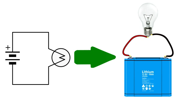
A battery connected to a light bulb or lamp is a useful example because it demonstrates the basic elements found in many circuit diagrams. The circuit consists of a battery, a light bulb, and wires connecting the two. When the circuit is complete and the battery provides a suitable voltage, current flows through the bulb, causing it to light.
The diagram below uses symbols to represent the battery and light bulb. Lines represent the electrical connections between them. These are the wires joining the positive terminal of the battery to the bulb or lamp, and negative terminal of the battery other terminal of the light bulb or lamp.
Although the drawing may look different from the actual circuit, both represent the same electrical arrangement. Circuit diagrams are often arranged with power to the circuit at the left and the output from the circuit at the right. This is why the circuit diagram at the left below looks like it is lying on its side compared to the physical circuit at the right. Although the diagram is oriented differently, it still has the same electrical connections as the physically built circuit.
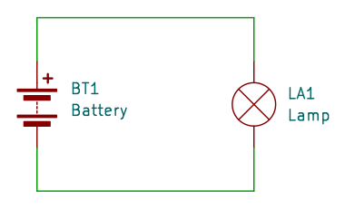
Some symbols may be drawn slightly differently, but still represent the same electrical or electronic component. For example, the circuit below is the same circuit as above, but the symbols used look slightly different. The Symbol to the left of the circuit below still represents a battery, and the symbol to the right still represents a lamp or light bulb.
Circuit Diagram Symbols and Physical Components
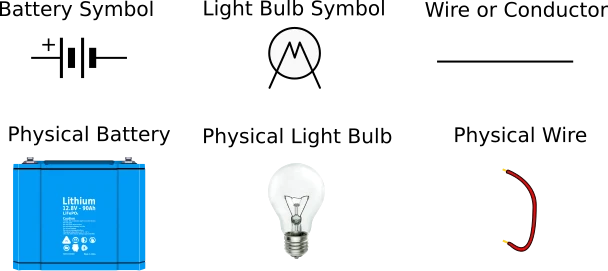
Each symbol in a circuit diagram represents a physical component or an electrical connection, for example:
- A battery symbol represents a battery or connected cells.
- A lamp symbol represents a light bulb or lamp.
- A straight line represents a wire or electrical conductor.
- A resistor symbol represents a component that provides electrical resistance.
- An LED symbol represents a light-emitting diode.
- A switch symbol represents a device that opens or closes a circuit.
The appearance of some symbols varies depending on the drawing standard used. For example, resistors may be represented by a rectangular symbol or a zigzag line. Both forms are widely used in circuit diagrams.
Learning common circuit diagram symbols makes it much easier to understand a schematic without needing a picture of every physical component. The image below shows the schematic symbols of the parts from the previous circuits, and the physical components or parts that they represent.
How the Circuit Diagram Relates to a Physical Circuit
The physical circuit built from a schematic may look quite different from the diagram.
On a breadboard, components might be arranged in rows, with jumper wires connecting them through internal metal contacts. On a printed circuit board (PCB), components may be soldered into place, with copper tracks providing the electrical connections.
A schematic does not normally show these physical details. Instead, it shows which terminals must connect electrically.
This distinction is important when building electronic projects. You do not usually need to position components in the same arrangement shown in the schematic. You need to reproduce the correct electrical connections and observe any requirements for component orientation, polarity, or physical placement.
How to Read Circuit Diagrams: Component Values and Reference Designators
Circuit diagrams often include letters, numbers, and other text alongside the component symbols. These markings help identify individual components and specify their electrical characteristics.
Understanding Component Values
A component symbol tells you what type of component is used, while its value tells you more about its electrical properties. For example, a resistor symbol may have the value 1kΩ written beside it. This means the resistor has a nominal resistance of one kilo ohm or 1,000 ohms.
Common component values include:
| Component | Example marking | What it means |
|---|---|---|
| Resistor | 1 kΩ | Resistance of 1,000 ohms |
| Capacitor | 100 µF | Capacitance of 100 microfarads |
| Inductor | 10 mH | Inductance of 10 millihenries |
| Battery | 9 V | Nominal battery voltage of 9 volts |
| LED | Red, 5 mm | LED color and physical size, if specified |
| Crystal | 16 MHz | Nominal oscillation frequency of 16 megahertz |
These are examples of component specifications, not complete ordering details. A practical circuit may also require information about power ratings, voltage ratings, tolerances, package sizes, and other characteristics.
Component values are particularly important when building a circuit. Substituting a component with an unsuitable value or rating may prevent the circuit from working correctly or damage a component.
Understanding Component Reference Designators
A reference designator is a short label used to identify an individual component in a schematic. It allows the designer to refer to a particular component in instructions, a parts list, or troubleshooting notes.
Common reference designators include the following:
| Reference Designator | Component Type | Example |
|---|---|---|
| R1, R2, R3 | Resistor | R1 is a 1 kΩ resistor |
| C1, C2, C3 | Capacitor | C1 is a 100 µF capacitor |
| D1, D2 | Diode or LED | D1 is a red LED |
| Q1, Q2 | Transistor | Q1 is an NPN transistor |
| L1, L2 | Inductor or sometimes lamp | L1 is a 10 mH inductor |
| SW1, SW2 | Switch | SW1 is a push-button switch |
| U1, U2 | Integrated circuit | U1 is a timer IC |
| J1, J2 | Connector | J1 is a power connector |
| Y1, Y2 or X1, X2 | Crystal or resonator | Y1 is a 16 MHz crystal |
| BAT1 or BT1 | Battery | BAT1 is a 9 V battery |
Reference designators are conventions rather than universal rules for every drawing. For example, the letter L may identify an inductor in one schematic or a lamp in another. Always consider the symbol, the component list, and the conventions used in the particular design.
The numbers distinguish components of the same general type. If a schematic contains three resistors, they might be labeled R1, R2, and R3. The following circuit diagram shows the battery and light bulb circuit with reference designators added. That is, BAT1 for the battery, and L1 for the light bulb or lamp.

Using a Parts List with a Circuit Diagram
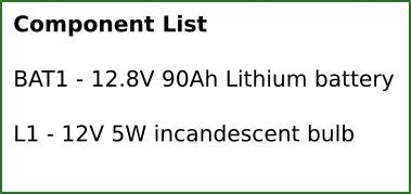
A schematic may be accompanied by a bill of materials (BOM), also called a parts list. This identifies the components required to build the circuit. For example, a very simple component list or parts list for the previous circuit diagram may specify the parts as follows, using the reference designators to identify the parts in the diagram.
Another example of a bill of materials for a simple LED circuit is shown in the table below.
| Reference | Component | Value or specification | Quantity |
|---|---|---|---|
| BT1 | Battery | 9 V | 1 |
| R1 | Resistor | 1 kΩ, suitable power rating | 1 |
| D1 | LED | Red LED | 1 |
| SW1 | Switch | SPST switch | 1 |
The reference designators connect the parts list above to the schematic shown below. If the instructions tell you to check R1, you can find that label in the diagram and identify the corresponding resistor in the parts list. As another example, look at the switch in the diagram below. It has a reference designator of SW1. Look this up in the above table and we see that it is a SPST switch. SPST stands for Single Pole Single Throw, and is a type of switch that connects or breaks conduction through a single wire, with only open and closed positions. For more examples of simple circuits for beginners when learning how to read circuit diagrams, see the simplest circuit article.
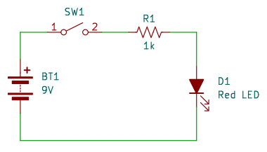
When sourcing components, check that the physical parts match the specified values, ratings, and package requirements. For polarized components, such as many LEDs and electrolytic capacitors, also check the required orientation.
How to Read Circuit Diagrams: Wire Connections and Junctions
Understanding how wires connect is one of the most important skills when learning how to read circuit diagrams.
A schematic uses lines to represent electrical conductors. Where those lines meet, the drawing indicates whether the corresponding conductors are electrically connected.
What Is a Node in a Circuit Diagram?
A node is an electrical connection point shared by two or more conductors. In many schematics, a filled dot indicates a junction where wires are electrically connected.
For example, if three wires meet at a junction, all three are electrically connected at that point. They share the same electrical node.
This convention is useful because a single connection point can connect several components without requiring every wire to be drawn directly from one component to another.
Some diagrams omit dots where only two wires meet because the connection is already clear. Therefore, the absence of a dot does not always mean that two wires are disconnected. Follow the drawing conventions used in the schematic.
A typical connecting node dot is shown at the top left of the diagram below. The diagram also shows 3 wires connected by a node, and 4 wires connected by a node. Two wires cross at the bottom of the diagram and are not connected. This is shown by the absence of a node at the point where the wires cross.

How to Identify Crossing Wires
When reading circuit diagrams, pay particular attention to wires that cross.
Depending on the drawing convention, crossing lines may represent separate conductors or an electrical connection. A filled junction dot is a common indication that the wires are connected.
Some schematics also use a small bridge or curved crossover to show that one wire passes over another without making an electrical connection.
Use these general guidelines:
- Lines meeting at a filled dot: The wires are electrically connected.
- Lines crossing without a connection marker: They may be unconnected, depending on the schematic’s conventions.
- A crossover bridge: The wires cross without connecting.
- A clearly drawn junction: The connected wires share an electrical node.
Do not rely on the presence or absence of a dot alone when the drawing is ambiguous. Check the schematic’s legend or connection conventions if necessary.
Understanding Connections Through Labels
Larger schematics can become difficult to read when many wires cross the page. Designers often use named nets, power symbols, and ground symbols instead of drawing every connection as a continuous line.
For example, two points marked GND are normally intended to connect to the same ground net, even if no continuous wire is drawn between them. Similarly, points labeled +5V may belong to the same 5 V supply net.
The following diagram comes from the circuit diagram of an Arduino Uno R3 board. It is the power section with the barrel power connector at the left of the diagram. At the bottom of the diagram are five different ground symbols marked GND. Each of these symbols connect to a common ground point, which means that the also connect to each other.
If you look at the full Arduino Uno R3 circuit diagram, you will see other +5V symbols like the one near the top right of the image below. These are also all connected together because they have the same label and connect to a common +5V point or net.
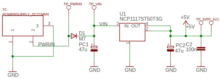
A net is a group of electrically connected points. Named nets help simplify a diagram and make complicated circuits easier to follow.
Remember that ground is a reference point in a circuit and is not necessarily connected to the earth. Its exact role depends on the circuit design.
How to Read Circuit Diagrams: Series and Parallel Circuits
Series and parallel circuits are useful examples for learning how to interpret connections and understand how components affect one another.
How to Read a Series Circuit Diagram
In a series circuit, components are connected along a single current path. The same current flows through every component in that path.
Consider a circuit containing a battery and two light bulbs connected in series as shown below. Current flows through the first bulb (L1) and then the second bulb (L2) before returning to the battery.
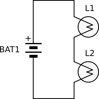
In an ideal series circuit:
- The same current flows through each component.
- The supply voltage is divided among the components according to their electrical characteristics.
- If one component opens the circuit, current stops flowing through the entire series path.
For example, if one bulb fails open in a simple series string, both bulbs go out because the current path is broken.
When reading the schematic, look for a single continuous path through the components. You do not need a junction dot when two wires simply join end to end and there is no ambiguity about the connection.
How to Read a Parallel Circuit Diagram
In a parallel circuit, components are connected across the same two electrical nodes. This creates separate branches through which current can flow.
For example, two light bulbs connected in parallel across a battery each have a connection to the positive supply node and a connection to the negative supply node. The following circuit shows two light bulbs wired in parallel to each other and to the battery.
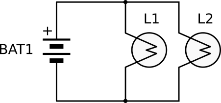
In an ideal parallel circuit:
- Each branch has the same voltage across it.
- The total current supplied is the sum of the currents flowing through the branches.
- An open circuit in one branch does not necessarily stop current from flowing through the other branches.
This is why parallel connections are common in electrical installations and electronic circuits.
When reading a parallel circuit diagram, identify the shared nodes first. If two components connect across the same pair of nodes, they are connected in parallel, even if their symbols appear in different parts of the drawing.
Series vs. Parallel Circuits
The following table compares features of series circuits with those of parallel circuits.
| Feature | Series Circuit | Parallel Circuit |
|---|---|---|
| Current paths | One path | Multiple branches |
| Current | Same through each component in the series path | Divides among branches |
| Voltage | Divided among components | Same across each branch |
| Open component | Can interrupt the entire path | Usually interrupts only its own branch |
| Typical example | Components in a simple series string | Household loads connected across a supply |
These principles apply to ideal circuit arrangements. Real circuits can behave differently because of internal resistance, component characteristics, and other practical effects.
How to Read Circuit Diagrams: Common Electronic Symbols
Learning the common electronic schematic symbols makes it easier to recognize what a circuit is designed to do.
The table below introduces several symbols you will encounter when studying basic electronics. The descriptions explain what each symbol represents and how the component is commonly used.
| Component | Symbol | What It Does | Where You Might Find It |
|---|---|---|---|
| Battery |  | Supplies electrical energy | Portable circuits and battery-powered projects |
| Resistor |  | Limits current or helps set voltages | LED circuits, voltage dividers, signal circuits, and nearly every electronic circuit |
| Variable resistor |  | Provides adjustable resistance | Volume controls and calibration circuits |
| Capacitor |  | Stores charge and affects changing signals | Timing circuits, filters, and power supplies |
| Inductor |  | Stores energy in a magnetic field | Filters, switching converters, and oscillators |
| Diode |  | Conducts preferentially in one direction | Rectifiers and circuit protection |
| LED |  | Emits light when appropriately forward-biased | Indicators, displays, and lighting |
| Switch |  | Opens or closes an electrical path | Controls and input circuits |
| Transistor |  | Controls current or voltage in a circuit | Amplifiers and switching circuits |
| Operational amplifier |  | Amplifies the difference between its input voltages | Signal conditioning and analog circuits |
| Integrated circuit (555) |  | Combines multiple electronic functions in one device | Timers, logic circuits, and microcontrollers |
| Crystal or resonator |  | Provides a frequency reference | Clock circuits and oscillators |
| Ground symbol |  | Marks a circuit reference or ground net | Most electronic schematics |
| Connector |  | Provides a connection to another circuit or device | Power inputs, sensor interfaces, and external wiring |
The exact shape of each symbol depends on the component and the drawing standard. A component may also have multiple symbols to represent different functions or operating conditions.
Resistors, Capacitors, and Inductors
Resistors, capacitors, and inductors are passive components that appear frequently in electronic schematics.
A resistor limits current or establishes a voltage relationship with other components. Its resistance is usually specified in ohms. See the articles How Does a Resistor Work? and Resistors in Parallel for more information on resistors and how to use and connect them.
A capacitor stores electrical charge and opposes changes in voltage. It is commonly used for filtering, coupling signals, and timing. See Capacitors for Beginners and the Capacitor Guide for Beginners for more information on capacitors.
An inductor stores energy in a magnetic field and opposes changes in current. Inductors are commonly found in filters and switching power supplies.
When reading a schematic, check the value beside each symbol. Two different resistors, capacitors, or inductors can have different effects on the circuit depending on their values and how they are connected.
Diodes, LEDs, and Transistors
Diodes and transistors are semiconductor devices that can control current flow.
A standard diode conducts readily in its forward direction under suitable conditions and blocks current in the reverse direction, subject to its ratings and operating limits. See our Diode Quick Reference for Beginners for the basics on diodes. See our diodes article for more detailed information, including on how they work in circuits.
An LED is a type of diode that emits light when forward current flows through it. Our Light Emitting Diode article has more details on how LEDs work.
A transistor can be used as an electronic switch or an amplifier. Different transistor types have different symbols, terminal arrangements, and operating characteristics. For more information on transistors, see the following articles:
- Transistors Explained: Everything You Need to Know
- What Is a Transistor? The Most Important Component
- Transistor History: A Breakthrough That Shaped Tech
When reading these symbols, look for polarity marks and terminal labels. An LED, for example, has an anode and a cathode, and reversing its orientation in a simple DC circuit will generally prevent it from lighting.
Integrated Circuits and Pin Numbers
Integrated circuits, or ICs, are often shown as rectangles with labels identifying the device and its pins.
For example, a 555 timer IC may be labeled U1, with its eight pins identified by number and sometimes by function. These pins might include trigger, threshold, output, discharge, reset, control voltage, and power connections.
A schematic may show only the connections relevant to the circuit. You should consult the manufacturer’s datasheet to confirm the pin functions, supply voltage requirements, and other operating limits.
When building a circuit, do not assume that pin positions can be inferred from the rectangle alone. Use the pin numbers and the datasheet for the exact IC.
How to Read Circuit Diagrams: Power Supplies and Ground Connections
Power supply and ground symbols are common in electronic schematics. Recognizing them helps you identify where a circuit receives power and how its electrical reference points are connected.
Understanding Power Supply Symbols
A circuit diagram may show a battery symbol or use a label such as +5V, +12V, or VCC to identify a power supply connection. These labels indicate the intended supply voltage or supply rail, but the exact meaning depends on the circuit.
For example, a microcontroller circuit might use a 5 V supply for its input and output circuitry while another section operates at 3.3 V. The schematic should identify the relevant supply connections.
Some schematics use power symbols rather than drawing a complete wire from the power source to every component. Components connected to the same named supply net are electrically connected through that net, even when the drawing does not show a continuous wire.
Understanding Ground Symbols
Ground symbols identify a circuit’s reference node. In many electronic circuits, this is the common return path for the power supply.
A schematic may contain several ground symbols in different locations. These normally represent connections to the same ground net unless the diagram explicitly distinguishes separate grounds.
For example, an LED circuit might connect the LED and resistor between a positive supply and ground. A microcontroller circuit might use the same ground reference for the microcontroller, switches, and sensors.
However, some designs use separate analog, digital, or isolated grounds. In these cases, follow the schematic carefully rather than assuming that every ground symbol is interchangeable.
How to Read Circuit Diagrams: Practical Example of an LED Circuit
A simple LED circuit brings together several of the principles covered in this guide. For example the circuit below containing a 9V battery, a resistor, and an LED connected in series.
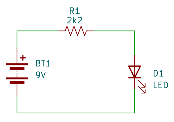
The schematic shows the electrical path from the positive battery terminal through the resistor and LED, returning to the negative battery terminal.
Here is how to interpret it:
- Identify the battery symbol and its voltage rating.
- Find the resistor symbol and read its resistance value.
- Identify the LED symbol and determine its polarity.
- Follow the connecting lines to confirm that the resistor and LED are connected in series.
- Check that the resistor is suitable for limiting the LED current.
- Use the schematic and component datasheets to build the circuit correctly.
The resistor is essential because an LED generally requires current limiting. Connecting an LED directly across a 9V battery can destroy it.
For an approximate resistor calculation, use Ohm’s law:
Where:
- is the required resistance in ohms.
- is the supply voltage.
- is the LED’s forward voltage.
- is the desired LED current in amperes.
For example, if the supply voltage is 9V, the LED forward voltage is 2V, and the target current is 10mA, the calculated resistance is:
A standard 750Ω resistor would give an approximate current of 9.3mA under these assumed conditions. A suitable power rating must also be selected, and the LED’s datasheet should be checked before construction.
This example demonstrates why learning how to read circuit diagrams is useful. The schematic does more than identify the components. It shows how they connect and provides the information needed to build a functioning circuit.
How to Read Circuit Diagrams: Common Drawing Conventions
Circuit diagrams follow conventions that make them easier to read and share. Understanding these conventions helps prevent mistakes when interpreting a schematic.
Common conventions include:
- Straight connecting lines: Wires are generally drawn horizontally or vertically for clarity.
- Consistent component orientation: Symbols are normally placed horizontally or vertically where practical.
- Reference designators: Components are labeled so they can be identified in the schematic and parts list.
- Connection dots: Junction dots indicate electrical connections where needed.
- Named nets: Labels such as
GND,VCC, andSDAidentify groups of connected points. - Functional grouping: Related components are often placed near one another to make the circuit’s operation easier to understand.
- Power and ground symbols: These simplify drawings by avoiding repeated supply and return wires.
The physical arrangement of components is not necessarily the same as their arrangement in the schematic. A resistor drawn beside an IC may be physically located elsewhere on the circuit board, provided its electrical connections are correct and any relevant physical design requirements are met.
You should also remember that different schematic standards and software packages can use different symbol styles. If a symbol is unfamiliar, consult the diagram’s legend, component documentation, or relevant schematic standard.
Consult the following articles and look at their circuit diagrams for more examples. Use any of the circuits in the articles below and follow along with the tips in the next section. For example, identify the different components in the circuits, find the power supply, and so forth.
- 555 Timer Circuits
- Easy Op Amp Oscillator
- Simple LED Flasher Circuit
- Easy 555 Project: Best Running LED CD4017 Solder Kit
Tips on How to Read Circuit Diagrams
The following tips can help you become more confident when interpreting electronic schematics.
- Start with simple circuits. Begin with a battery, resistor, LED, and switch before attempting complex electronic designs.
- Learn the common symbols. Familiarize yourself with resistors, capacitors, diodes, transistors, switches, and integrated circuits.
- Identify the power supply first. Determine the supply voltage and locate the power and ground connections before tracing the rest of the circuit.
- Follow connections carefully. Trace each wire between component terminals and pay attention to junctions and net labels.
- Read the reference designators. Use labels such as R1, C1, and U1 to distinguish components of the same type.
- Check component values. A resistor’s value, a capacitor’s capacitance, and an IC’s part number can determine whether the circuit works correctly.
- Use datasheets. Manufacturer datasheets provide pinouts, electrical specifications, recommended operating conditions, and component limitations.
- Compare the schematic with the physical circuit. If you are building a project, use the schematic alongside the breadboard layout or PCB diagram where available.
- Trace one section at a time. In a complex schematic, focus on the power supply, input stage, processing section, or output stage separately.
- Practice by building circuits. Constructing simple circuits helps you connect schematic symbols with real components and their electrical behavior.
- Do not assume every crossing is a connection. Check for junction dots, crossover symbols, and named nets.
- Observe safety precautions. Before building a circuit, verify its supply voltage and current requirements. Mains-powered circuits require appropriate safety knowledge and should not be treated like low-voltage breadboard projects.
A particularly useful habit is to explain the function of each component while tracing the circuit. For example, you might identify a resistor as a current-limiting component, a capacitor as part of a timing network, or a transistor as a switch. This helps you move beyond recognizing symbols toward understanding the complete design.
Did You Know?
Circuit diagrams are more than simple drawings. They are a practical way of communicating how electrical and electronic systems work.
Here are some useful facts about schematics.
- The physical layout can be completely different. A schematic may show components arranged for clarity rather than according to their positions on a breadboard or PCB.
- A single net can connect many components. Named connections such as
GNDallow a designer to show electrical connections without drawing every wire across the page. - Symbols can vary between standards. For example, resistors are commonly drawn as rectangles in IEC-style (EU standard) diagrams and as zigzag lines in many ANSI-style (USA standard) diagrams.
- A schematic can describe a circuit that has not been built yet. Engineers use schematics to plan, analyze, simulate, and communicate circuit designs before assembling hardware.
- The same schematic can lead to different physical implementations. A circuit may be built using a breadboard, a soldered prototype, or a printed circuit board while retaining the same basic electrical connections.
- Modern electronics software can generate schematics and PCB layouts. Electronic design automation tools help designers create circuit diagrams, check electrical connections, and prepare board layouts for manufacturing.
These facts explain why learning to read schematics is such a valuable foundation for electronics. The skill applies to simple battery circuits, electronic kits, microcontroller projects, and more advanced engineering designs.
Frequently Asked Questions
What is a circuit diagram?
A circuit diagram is a drawing that uses symbols and connecting lines to represent an electrical or electronic circuit. It shows which components are connected and how they relate electrically. Circuit diagrams are also called schematic diagrams or schematics.
How do beginners learn how to read circuit diagrams?
Beginners should start with simple circuits containing a battery, resistor, LED, and switch. Learn the symbols, identify component values, and trace the connections between terminals. Building the same circuit on a breadboard is an effective way to connect the diagram with a real working circuit.
What is the difference between a circuit diagram and a schematic?
The terms are often used interchangeably in electronics. A schematic emphasizes the electrical connections and functions of components rather than their physical positions. A physical layout or wiring diagram, by comparison, may show where components are placed and how wires should be routed.
How do you know if wires are connected in a circuit diagram?
A filled dot at a junction commonly indicates that wires are electrically connected. Lines that cross without a connection marker may represent separate conductors, depending on the drawing convention. Named nets and power symbols can also indicate connections between points that are not joined by a continuous line.
What do R1, C1, D1, and U1 mean in a schematic?
These are reference designators. R1 commonly identifies a resistor, C1 a capacitor, D1 a diode or LED, and U1 an integrated circuit. The number distinguishes each component from other components of the same general type. The schematic’s legend or parts list can clarify any unusual designations.
Do circuit diagrams show the actual position of components?
Usually not. A schematic is arranged to make the electrical connections and circuit operation easy to understand. The components may be positioned differently on a breadboard or PCB. For physical assembly, you may also need a wiring diagram, breadboard layout, or PCB layout.
What is the difference between series and parallel connections?
In a series circuit, components share a single current path, so the same current flows through each component in that path. In a parallel circuit, components connect across the same two nodes, so they have the same voltage across them. Current divides among the parallel branches.
Where can I find a list of electronic schematic symbols?
You can find electronic schematic symbols in electronics textbooks, component datasheets, schematic software libraries, and beginner electronics reference guides.
What should I do if I do not recognize a symbol?
Check the schematic’s legend, component list, and accompanying documentation. If the symbol is labeled with a reference designator or part number, use that information to locate the relevant datasheet. Also check which schematic standard is being used, because some symbols differ between standards.
Final Thoughts on Learning How to Read Circuit Diagrams
Learning how to read circuit diagrams is one of the most useful skills for anyone starting with electronics. By recognizing common symbols, understanding component values and reference designators, and tracing electrical connections, you can interpret schematics and use them to build working circuits.
Start with a simple battery and light bulb circuit, then progress to series and parallel circuits before moving on to resistors, LEDs, transistors, and integrated circuits. As you gain experience, you will find it easier to understand more complicated designs and troubleshoot problems.
By studying schematics and building the circuits they describe, you will gradually develop the knowledge and confidence needed to work with a wide range of electronic projects.