
A blinking LED circuit is a useful beginner electronics project that demonstrates how transistors, resistors, and capacitors can work together to produce a repeating flashing effect without a microcontroller. This circuit uses two PNP transistors connected as an astable multivibrator to flash two different colors from a single three-pin, common-cathode tricolor LED. It is a practical project for learning about transistor switching, capacitor charging, timing circuits, and basic electronic oscillators.
What Is a Blinking LED Circuit?
A blinking LED circuit is an electronic circuit that repeatedly switches an LED on and off. In this project, two LEDs housed inside one tricolor LED package switch on alternately, producing a two-color flashing effect. It is similar to the simple LED flasher circuit that uses two LEDs.
The circuit uses a transistor astable multivibrator, which generates a repeating sequence of switching signals without requiring a clock signal, microcontroller, or dedicated timer IC. The following video demonstrates the circuit working.
The main features of this blinking LED circuit are:
- Two PN2907 PNP transistors. The LED flasher circuit uses two NPN transistors.
- One three-pin, common-cathode tricolor LED.
- Four resistors and two capacitors.
- A recommended 9V battery supply, with a nominal operating range of approximately 5 V to 12 V, subject to component selection.
- Alternating illumination of two LED colors.
- A flashing rate determined mainly by the resistor and capacitor values.
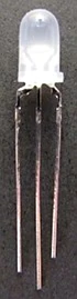
The circuit is suitable for construction on a solderless breadboard and is a useful introduction to transistor-based oscillators. The following image shows the tricolor LED used in this project.
Blinking LED Circuit Diagram
The schematic below shows two PNP transistors connected in an astable multivibrator configuration. The capacitors couple the output of each transistor stage to the base of the other transistor, while the resistors establish the transistor bias and limit the LED current.
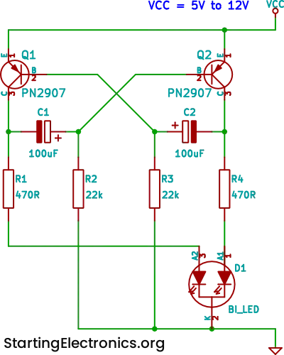
The main connections are as follows:
- Power supply: The transistor emitters connect to the positive supply rail.
- LED: The common cathode connects to the negative supply rail, while each LED anode is driven by its own transistor output through a current-limiting resistor.
- Transistor bias resistors: These establish the base bias needed for the transistors to switch.
- Cross-coupling capacitors: Each capacitor couples a collector transition to the base of the opposite transistor, helping the circuit alternate between its two states.
The two transistors do not remain on simultaneously during normal operation. Instead, they switch alternately, so one LED color illuminates while the other is off.
How the Blinking LED Circuit Works
The operation of this circuit becomes easier to understand when you consider the two transistors as electronic switches. Each transistor controls one of the LED’s internal light-emitting elements.
The capacitors provide the timing action that causes the switches to alternate.
1. One transistor switches on
When power is first applied, small differences in transistor characteristics and capacitor charge usually cause one transistor to conduct more strongly than the other.
Because the PN2907 is a PNP transistor, it turns on when its base is sufficiently lower in voltage than its emitter. With the emitter connected to the positive supply, current can flow from the emitter to the collector and then through the corresponding LED branch.
The LED connected to that transistor lights up.
2. The capacitor changes the opposite transistor’s state
As the conducting transistor’s collector voltage changes, the coupling capacitor transfers a voltage change to the base of the other transistor.
This temporarily changes the voltage at that base and helps keep the opposite transistor switched off.
Meanwhile, the capacitor charges or discharges through the surrounding resistors. The base voltage gradually moves toward the point where the opposite transistor can begin conducting.
3. The transistors exchange states
Eventually, the capacitor voltage changes enough for the previously off transistor to turn on. Its collector voltage then changes, and the other coupling capacitor drives the first transistor toward cutoff.
The first LED switches off and the second LED switches on.
4. The sequence repeats
The two transistors continue exchanging states as the capacitors charge and discharge. The result is a repeating sequence in which the LED changes between its two colors.
This repeating action is why the circuit is called an astable multivibrator. An astable circuit has no stable resting state, so it continually changes between its two switching states while power is applied.
Understanding the Flashing LED Schematic
A flashing LED schematic may appear complicated at first, but each component has a specific job. Understanding these jobs makes the circuit easier to build, modify, and troubleshoot.
| Component | Quantity | Function |
|---|---|---|
| PN2907 PNP transistor | 2 | Alternately switches the LED branches |
| Resistor | 4 | Two establish transistor bias; two limit LED current |
| Capacitor | 2 | Provide timing and cross-coupling between the transistor stages |
| Common-cathode tricolor LED | 1 | Produces the two alternating colors |
| DC power supply | 1 | Provides energy for the circuit |
Why are two transistors needed?
A single transistor can switch an LED on and off when controlled by an external signal, but this project needs a circuit that generates its own repeating signal.
The two transistors provide the two interacting switching stages required for the astable multivibrator. Each stage helps trigger the other, creating continuous oscillation.
What do the four resistors do?
The resistors have two different functions.
Two resistors provide the base-bias paths that help establish the transistor switching behavior. The other two are connected in series with the LED branches to limit current.
The LED current-limiting resistors are especially important. Without them, excessive current could damage the LED or the transistors.
Why are two capacitors needed?
Each capacitor couples a voltage transition from one transistor’s collector to the opposite transistor’s base. This coupling helps switch the transistors alternately.
The capacitors also introduce a time delay because their voltages change gradually through the resistors. Increasing the capacitance generally increases the time between switching events, while decreasing it generally makes the circuit flash faster.
Why use PN2907 PNP transistors?
The PN2907A is a PNP bipolar junction transistor that can be used as a high-side switch. In this circuit, the emitters connect to the positive supply, making the devices suitable for driving the two LED anodes while the LED shares a common cathode connected to ground.
The PNP arrangement is important because a common-cathode LED has both internal LED cathodes joined together. A circuit designed for a common-anode LED would require different connections and might use a different transistor arrangement.
Always check the transistor datasheet for the pinout of the specific part you have. Do not assume that every transistor in a similar package has the same emitter, base, and collector arrangement.
Choosing a Tricolor LED for the Blinking LED Circuit
The LED is an important part of this project because the circuit is designed to alternate between two colors from a single component.
A tricolor LED contains two LED elements in one package. Depending on the internal arrangement and the number of pins, it can produce two individual colors and a third color when both elements are illuminated together.
The original project uses a Kingbright L-59EGW LED, which contains red and green LED elements. When the red element is illuminated, the LED appears red. When the green element is illuminated, it appears green. If both elements are switched on together, their light mixes to produce a yellowish or orange-yellow appearance, depending on the LED and viewing conditions.
This circuit switches between the two individual colors rather than illuminating both elements simultaneously. The mixed color is therefore not used in this particular circuit.
Common-cathode versus common-anode LEDs
Before buying an LED, check its datasheet to establish whether it is common-cathode or common-anode.
| LED Type | Internal Connection | Suitability for This Circuit |
|---|---|---|
| Common-cathode | Both LED cathodes connect to one shared pin | Suitable |
| Common-anode | Both LED anodes connect to one shared pin | Not directly suitable without redesigning the circuit with NPN transistors |
| Two-pin, antiparallel bi-color LED | Two LED elements are connected in opposite directions | Not suitable for this circuit’s three-pin arrangement |
A three-pin LED is not automatically a common-cathode device. The shared pin must be identified correctly before connecting the LED to the circuit.
For the common-cathode LED used here, the shared cathode connects to the negative supply rail, and each individual anode connects to its own transistor-controlled branch through a current-limiting resistor.
Identifying the LED pins
Do not rely entirely on the length of the leads or the shape of the LED package to identify its connections. These features can vary between manufacturers and product families.
Instead:
- Find the LED’s part number.
- Consult the manufacturer’s datasheet.
- Identify the common cathode and the two individual anodes.
- Confirm the forward-voltage specifications and recommended operating current.
- Check the connections before applying power.
If the exact LED used in the original project is unavailable, a compatible common-cathode red-green LED can be substituted, provided its electrical specifications suit the circuit.
Building the Blinking LED Circuit on a Breadboard
A solderless breadboard is a convenient way to construct and test the circuit. It allows you to change component values and correct wiring errors without soldering.
Components required
Gather the following components before starting.
| Component | Quantity | Notes |
|---|---|---|
| PN2907A PNP transistor | 2 | Or similar PNP transistors, check the pinout of your exact part |
| Common-cathode tri-color LED | 1 | Red and green are suitable example colors |
| Resistors | 4 | Two base-bias resistors and two LED current-limiting resistors |
| Capacitors | 2 | Choose values appropriate for the desired flashing rate |
| 9 V battery or suitable DC supply | 1 | Observe the circuit’s voltage limits |
| Solderless breadboard | 1 | For temporary construction |
| Jumper wires | As required | For supply and component connections |
Use the component values shown on the circuit schematic if you are reproducing the original design. If those values are unavailable or you want to experiment, choose suitable values based on the transistor characteristics, LED specifications, and supply voltage.
Step 1: Connect the power rails
Connect the breadboard’s positive rail to the positive supply and the negative rail to ground.
Keep the supply switched off while wiring the circuit. Breadboard power rails are sometimes split into separate sections, so check whether the rails need jumper wires to connect them electrically.
Step 2: Insert the transistors
Place the two PN2907A transistors on the breadboard so their leads do not accidentally share the same connected rows.
Identify each emitter, base, and collector from the appropriate datasheet. For a PNP transistor in this circuit, the emitter connects toward the positive supply, while the collector supplies current to its associated LED branch.
Incorrect transistor pin identification is a common reason a newly assembled circuit fails to operate.
Step 3: Connect the LED branches
Connect the common cathode of the tricolor LED to ground.
Connect each of the two individual LED anodes to the collector of its associated transistor through a current-limiting resistor. Each resistor must be selected for the LED forward voltage and the available supply voltage.
This arrangement allows each transistor to control one color independently.
Step 4: Add the bias resistors
Connect the two base-bias resistors according to the schematic. In the PNP astable multivibrator, these resistors provide paths that establish the base voltages and allow the switching cycle to develop.
The resistor values affect both the circuit’s operation and its timing. Use the specified values when reproducing a known design rather than substituting arbitrary resistors.
Step 5: Install the capacitors
Connect the two timing capacitors between the collector of each transistor stage and the base of the opposite stage, as shown in the schematic.
Check whether the selected capacitors are polarized. If using electrolytic capacitors, follow the polarity required by the actual circuit voltages and the manufacturer’s instructions.
Step 6: Check the wiring
Before applying power, check the following:
- The supply polarity is correct.
- Both transistor pinouts are correct.
- The LED’s common cathode connects to ground.
- Each LED branch has its own current-limiting resistor.
- The two capacitors connect to the correct opposite transistor stages.
- There are no accidental shorts between the supply rails.
- The supply voltage is within the circuit’s intended operating range.
Step 7: Apply power and observe the LED
Connect the power supply and observe the LED. The two colors should alternate, producing a repeating flashing effect.
If the LED remains off or only one color illuminates, disconnect the supply and check the wiring and component polarity before trying again.
Troubleshooting a Blinking LED Circuit
If your circuit does not flash as expected, check the power supply, transistor connections, capacitor wiring, and LED pinout before changing component values.
The following table covers common problems and their likely causes.
| Problem | Possible Cause | What to Check |
|---|---|---|
| Neither LED color lights | Incorrect wiring or reversed supply | Check the power rails, transistor pinouts, and LED connections |
| Only one color lights | One transistor stage is not switching, or one LED branch is faulty | Check the relevant transistor, resistor, and LED element |
| LED remains continuously on | Incorrect capacitor connections or a faulty transistor | Check the cross-coupling connections and transistor orientation |
| Flashing is too fast | Timing capacitances or resistances are too small | Increase the timing component values |
| Flashing is too slow | Timing capacitances or resistances are too large | Decrease the timing component values |
| Flashing is irregular | Loose connections, unsuitable components, or a weak supply | Check the breadboard wiring and supply voltage |
| One color is much brighter | Different LED forward voltages or unsuitable resistor values | Calculate and adjust each LED’s series resistance |
What if the circuit does not start oscillating?
A correctly connected astable multivibrator should normally begin oscillating when power is applied. Small differences between the transistors and the initial capacitor voltages help determine which stage switches first.
If oscillation does not begin, first check that the capacitors connect between the correct collector and opposite base. A capacitor connected to the wrong transistor stage can prevent the expected switching action.
Also verify that the transistor base-bias resistors connect to the correct supply rail. PNP transistor circuits require different bias arrangements from comparable NPN circuits.
Tips for Blinking LED Circuit Construction
These practical tips will help you build, test, and modify the circuit successfully.
- Check the LED type first. Use a common-cathode tricolor LED. A common-anode device requires a different circuit arrangement.
- Verify transistor pinouts by checking the PN2907A datasheet.
- Start with the recommended schematic values. The resistor and capacitor values work together, so changing several components simultaneously makes troubleshooting harder.
- Use current-limiting resistors. Each LED element needs appropriate current limiting to avoid damage.
- Check electrolytic capacitor polarity. Follow the actual circuit voltages and capacitor specifications.
- Use a stable power supply. A suitable regulated supply can make initial testing easier than a weak or partially discharged battery.
- Change timing components gradually. Try changing the capacitor values first if you want to experiment with the flashing speed.
- Avoid unnecessary long jumper wires. Short, tidy breadboard connections make the circuit easier to inspect and troubleshoot.
- Measure rather than guess. A multimeter can help you check the supply voltage and identify wiring faults. An oscilloscope can reveal the alternating collector voltages if the circuit does not behave as expected.
- Disconnect power before modifying the circuit. This reduces the risk of accidental shorts while moving components.
Did You Know?
A transistor astable multivibrator is one of the classic building blocks of electronics. Long before inexpensive microcontrollers became commonplace, circuits like this were used to generate repeating pulses, alternating lights, and simple timing signals.
An astable multivibrator is particularly useful because it generates its own oscillation. It does not require a separate clock source or a programmed controller.
The same basic principle can be applied to many projects, including:
- Alternating warning lights.
- Simple visual indicators.
- Model railway lighting effects.
- Demonstrations of capacitor charging and discharging.
- Introductory transistor switching experiments.
- Basic pulse-generating circuits.
Another interesting feature is that the flashing behavior comes from the interaction between the two transistor stages. Neither transistor needs to generate a complete oscillation independently. Each stage influences the other through the coupling capacitor, producing the repeating sequence.
The original project also demonstrates how one multi-color LED can replace two separate LEDs in a conventional two-transistor flasher. This reduces the number of LED packages needed while preserving the alternating-color effect.
Frequently Asked Questions About Blinking LED Circuits
How does a blinking LED circuit work without a microcontroller?
A transistor astable multivibrator generates its own repeating switching signal. Two transistors alternately conduct as the capacitors charge and discharge through the resistors. In this project, each transistor controls one color of the tricolor LED, creating a continuous flashing effect without software.
Can I use a different PNP transistor instead of the PN2907?
A suitable alternative PNP transistor may work if its voltage rating, current rating, power dissipation, and switching characteristics are appropriate for the circuit. However, the pinout may differ, so check the datasheet before substituting a component. A replacement must also be suitable for the chosen supply voltage and LED current.
Can I use an NPN transistor instead?
Not as a direct replacement in the same circuit. NPN transistors have different switching polarity and require a different bias arrangement. An NPN based astable multivibrator is possible, but its schematic and LED connections must be designed for NPN transistors.
Why does this blinking LED circuit use a common-cathode LED?
The circuit uses two PNP transistors to switch current from the positive supply into the two individual LED anodes. A common-cathode LED allows both LED elements to share a connection to the negative supply rail.
A common-anode LED has the opposite internal arrangement and cannot simply be connected in the same way.
Can I use a two-pin bi-color LED?
Not directly. A typical two-pin bi-color LED contains two LED elements connected in opposite directions. Its color depends on the direction of current through the device.
This project requires a three-pin LED with two independently accessible anodes and a shared cathode.
Can I make the LED flash faster or slower?
Yes. The resistor and capacitor values determine the approximate switching period. Increasing the timing capacitance generally slows the flashing, while decreasing it generally speeds up the flashing.
Changing the timing resistors also affects the switching period. For predictable results, change one component at a time and observe the effect.
Can I power the blinking LED circuit from a 5 V supply?
The circuit may operate from a 5 V supply, but you should verify the transistor bias conditions, LED current, and timing behavior at that voltage. The LED current-limiting resistors must be appropriate for the supply and the forward voltage of each LED element.
Do not assume that every component arrangement will operate reliably across the entire 5 V to 12 V range without checking the component values and specifications.
Why do the two LED colors have different brightness levels?
The two LED elements may have different forward voltages and light output at the same current. Their current-limiting resistors, LED characteristics, and viewing conditions all influence perceived brightness.
You can calculate separate resistor values for the red and green elements to bring their currents closer to suitable target values.
Is a blinking LED circuit the same as a flashing LED circuit?
Yes. The terms blinking LED circuit and flashing LED circuit generally describe circuits that repeatedly switch an LED on and off. Both terms are commonly used for projects involving transistor oscillators, timer ICs, and microcontrollers.
The exact circuit design determines whether the LED flashes at a fixed rate, alternates between colors, or follows a programmable pattern.
Can I use this circuit to flash two separate LEDs?
Yes, provided the two LED branches are connected appropriately and each LED has its own current-limiting resistor. The conventional two-transistor astable multivibrator commonly uses two separate LEDs, one controlled by each transistor.
The circuit described here uses a tricolor LED instead, allowing the two light sources to share one physical package.
Blinking LED Circuit Conclusion
This blinking LED circuit is a practical beginner electronics project that demonstrates how two PNP transistors, four resistors, and two capacitors can produce a repeating alternating-color effect. By using a three-pin common-cathode tricolor LED, the circuit achieves the behavior of a conventional two-LED astable multivibrator in a single LED package.
Understanding the schematic, transistor connections, capacitor timing, and LED current-limiting resistors makes the project easier to build and modify. Once the basic circuit works, experimenting with the timing components provides a way to learn more about transistor switching and oscillator behavior.
The project is also a good starting point for more advanced flashing-light designs, including warning indicators, multi-color LED effects, and circuits controlled by dedicated timer ICs or microcontrollers.