
A PNP transistor is a type of bipolar junction transistor (BJT) used for switching and amplifying electrical signals. It is commonly found in electronic circuits that control LEDs, relays, small motors, and other loads. Understanding the PNP transistor symbol, terminal connections, and operating principles will help you identify these components and use them correctly in practical circuits.
What Is a PNP Transistor?
A PNP transistor is a semiconductor device with three terminals: the emitter, base, and collector. It is made from three semiconductor regions arranged as P-type, N-type, and P-type material. The middle N-type region forms the base, while the two outer P-type regions form the emitter and collector.
A PNP transistor is often used as a high-side switch, where it controls the supply voltage delivered to a load. It can also amplify small electrical signals.
The key points to remember are:
- Emitter (E): Supplies conventional current into the transistor during normal operation.
- Base (B): Controls the transistor’s operation.
- Collector (C): Receives conventional current from the emitter through the transistor when it is switched on.
- Switching action: The transistor turns on when its base is sufficiently lower in voltage than its emitter.
- Amplification: A small base current can control a larger collector current within the transistor’s operating limits.
A PNP bipolar junction transistor works on the same basic principles as an NPN transistor, but the required voltage polarities and conventional current directions are reversed.
PNP Transistor Symbol
The schematic symbol identifies the transistor type and its three terminals. The most important feature to recognize is the direction of the arrow on the emitter.
A PNP transistor symbol has an arrow pointing inward, toward the base, as the symbol at the right of the image below shows. An NPN transistor symbol has an arrow pointing outward, away from the base, as the symbol at the left of the image below shows.
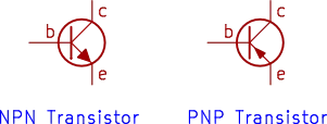
The arrow identifies the emitter and indicates the direction of conventional current through the emitter under normal forward-active operation. It is a useful way to distinguish the two transistor types when reading circuit diagrams.
The three terminals are:
- E: Emitter
- B: Base
- C: Collector
Does the PNP Transistor Symbol Have to Point in a Particular Direction?
No. The entire symbol can be rotated to make a circuit diagram easier to read. It might appear upside down, sideways, or in another orientation. In other words, the symbol is the same as in the above image, but can be rotated in any orientation in a circuit diagram. The arrow still points to the base and the symbol always looks the same, but rotation can vary. For an example of PNP transistors used in a circuit diagram, see the blinking LED circuit.
The direction in which the symbol is drawn does not change the transistor’s electrical operation. However, the emitter, base, and collector connections must still be identified correctly.
Do not confuse the orientation of the schematic symbol with the physical pin arrangement of the component.
PNP Transistor Pinout
A transistor pinout identifies the physical terminals of a transistor so that you can connect it correctly in a circuit.
The diagram below shows the original pinout illustration for a PN2907 PNP transistor, including the transistor symbol and its TO-92 plastic package.
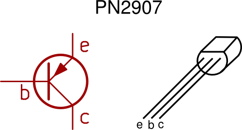
The diagram helps you relate the three terminals in the schematic symbol to the leads of the physical component. Other examples of transistors that are the PNP bipolar junction type are listed below with links to the manufacturer’s pages for the devices where the datasheet for each can be found. Datasheets show the pinout and other information for these transistors.
- PN2907A from onsemi
- 2N3906T from onsemi
- MMBT2907AL surface mount PNP from onsemi
- 2N2907 from Microchip
- 2N2907A datasheet from Diotec
Why the PNP Transistor Pinout Matters
The terminal arrangement depends on the specific transistor type, package, and sometimes the manufacturer. Two transistors that look similar might not have the same lead or pin order.
Before connecting a PNP transistor:
- Identify the complete part number printed on the component or specified in your parts list.
- Check the manufacturer’s datasheet for the correct package and pinout.
- Confirm the viewing direction shown in the datasheet, such as viewing the flat face of a TO-92 package.
- Match the emitter, base, and collector to the correct circuit connections.
- Check the component’s maximum voltage and current ratings before applying power.
Never assume that every TO-92 transistor has the same pin arrangement. A wrong connection may prevent the circuit from working and can damage the component.
Why Does the Transistor Symbol Sometimes Look Upside Down?
The PN2907 symbol in the pinout illustration might look different in orientation from the symbol used in the earlier comparison image. This is normal.
Schematic symbols can be rotated or repositioned to make circuit diagrams clearer. What matters is the identity of each terminal, not whether the symbol points upward or downward on the page.
The physical transistor must still be connected according to its actual pinout.
How a PNP Transistor Works
A PNP transistor operates by controlling current between its emitter and collector using a relatively small current at the base. Its operation depends on the voltage difference between the base and emitter.
For a typical silicon PNP transistor, the base must be approximately 0.6 to 0.7 V lower than the emitter for the base-emitter junction to conduct appreciably. The exact voltage depends on the transistor and its operating current.

Consider a PNP transistor with its emitter connected to a positive supply.
- Transistor off: The base is at approximately the same voltage as the emitter, so little current flows through the emitter-collector path.
- Transistor turning on: The base voltage is reduced relative to the emitter voltage, allowing base current to flow.
- Transistor on: Sufficient base current allows the transistor to conduct the required collector current, within its ratings.
For a switching application, the base is often pulled toward the positive supply to turn the transistor off and pulled toward a lower voltage to turn it on.
PNP Transistor Current Direction
Conventional current through a PNP transistor normally flows from the emitter to the collector when the device is conducting. The base current also flows out of the base terminal under the usual forward-active operating conditions. This is the opposite of the conventional current directions associated with an NPN transistor.
Remember that conventional current direction is defined as the direction positive charge would flow. The actual movement of electrons in semiconductor material is different.
Using a PNP Transistor as a Switch
One of the most common applications of a PNP transistor is switching a load connected to a positive supply. This arrangement is known as a high-side switch because the transistor controls the connection between the positive supply and the load.
For example, a PNP transistor can be used to switch an LED on and off as the following circuit diagram shows. This circuit allows an Arduino Uno to control a PNP type transistor which in turn switches and LED on and off.
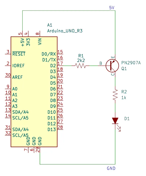
In a basic high-side switching circuit:
- Connect the emitter to the positive supply.
- Connect the collector to the load.
- Connect the other side of the load to ground or the negative supply.
- Use a suitable resistor and control signal to drive the base.
- Keep the base near the emitter voltage to switch the transistor off.
- Pull the base sufficiently below the emitter voltage to switch it on.
The base resistor limits base current and helps protect the transistor and the circuit driving it.
Important: Do not connect the base directly to a lower voltage without checking the circuit conditions. A base resistor is generally needed to limit current. Also, ensure that the control signal does not exceed the transistor’s maximum emitter-base voltage rating.
Choosing the Base Resistor
The base resistor depends on the supply voltage, the control voltage, the load current, and the transistor’s characteristics.
For reliable switching, the base current should be chosen to ensure that the transistor can carry the required load current in saturation. Do not simply use the transistor’s typical current gain as the design ratio for a saturated switch.
For example, suppose the emitter is connected to a 5V supply, the base is driven from a 0V control signal, and the estimated base-emitter voltage is 0.7V. The voltage across the base resistor is approximately:
If a base current of 2mA is appropriate for the application, the estimated resistance is:
A nearby standard resistor value could be 2.2kΩ, provided the resulting current is suitable for the transistor and the control circuit.
This is an illustrative calculation, not a universal resistor value. Always check the transistor’s datasheet and the output-current limits of the circuit driving its base.
PNP Transistor vs. NPN Transistor
PNP and NPN transistors are both bipolar junction transistors. They can perform similar functions, including switching and amplification, but they differ in polarity, conventional current direction, and typical circuit arrangements.
| Feature | PNP Transistor | NPN Transistor |
|---|---|---|
| Semiconductor arrangement | P-N-P | N-P-N |
| Emitter arrow | Points inward | Points outward |
| Typical switching arrangement | High-side switching | Low-side switching |
| Base voltage to turn on | Lower than emitter | Higher than emitter |
| Conventional emitter-collector current | Emitter to collector | Collector to emitter |
| Typical base current | Flows out of base | Flows into base |
The choice between a PNP transistor and an NPN transistor depends on the circuit design. NPN transistors are often convenient for low-side switching because a control signal can turn them on by raising the base voltage above the emitter voltage.
A PNP transistor is useful when the load needs to be switched from the positive supply side. However, the control circuit must be able to provide the required base voltage and current.
Neither type is universally better. The correct choice depends on the required switching arrangement, supply voltage, load current, and control circuitry.
Common PNP Transistor Types: PN2907, 2N3906, and 2N2907
Several PNP transistor types are used in general-purpose electronic circuits. The PN2907, 2N3906, and 2N2907 are examples that may be encountered in electronics projects and component references.
Although they belong to the same broad category, they are not automatically interchangeable.
| Transistor | General description | What to check before use |
|---|---|---|
| PN2907 | General-purpose PNP transistor designation | Exact datasheet, package, pinout, and ratings |
| 2N3906 | Common small-signal PNP transistor | Collector current, voltage ratings, gain, and package |
| 2N2907 | General-purpose PNP transistor designation | Exact version, package, pinout, and ratings |
The suffix and manufacturer can matter. For example, a 2N2907A is a related designation, but its specifications should not be assumed to be identical in every respect to every device labeled 2N2907.
The PN2907
The PN2907 is a PNP transistor that can be used in suitable switching and amplification circuits. The original pinout illustration accompanying this article identifies the emitter, base, and collector. This transistor is available as the PN2907A from onsemi.
Use the illustration on this page as a guide to the particular device it represents, but confirm the pinout against the datasheet for the exact part you have.
The 2N3906
The 2N3906 is a widely used small-signal PNP transistor. It is suitable for many low-power switching and signal-amplification applications when its electrical ratings meet the circuit requirements. This transistor is available as the 2N3906T from onsemi.
It can be useful in beginner electronics experiments involving control signals, indicators, and other modest loads. However, the allowable current, voltage, and power dissipation must be checked before use.
The 2N2907
The 2N2907 is another PNP transistor used in switching and amplification circuits. It is related to the PN2907 designation, but you should verify the specific manufacturer’s documentation rather than assuming that all devices with similar names have identical pinouts or ratings. This transistor is available as the 2N2907 from Microchip, 2N2907A from Diotec, and as the surface mounting MMBT2907AL from onsemi.
For any of these transistors, consult the datasheet for the exact component before substituting it into an existing circuit.
Tips for PNP Transistors
These practical tips can help you avoid common problems when using PNP transistors in electronic projects.
- Check the arrow. The inward-pointing emitter arrow is the quickest way to distinguish a PNP symbol from an NPN symbol.
- Identify the terminals. Make sure you can distinguish the emitter, base, and collector before wiring the circuit.
- Verify the pinout. Never assume that two transistor packages have the same lead arrangement.
- Use a base resistor. Limit the base current when driving the transistor from a supply or control output.
- Check the polarity. A PNP transistor generally turns on when its base is sufficiently lower in voltage than its emitter.
- Check the ratings. Confirm the maximum collector current, voltage limits, power dissipation, and temperature requirements.
- Allow for heat. A transistor dissipates power while conducting. Check whether the package can safely dissipate the expected power.
- Consider the control signal. When switching a higher positive supply with a lower-voltage microcontroller, you may need additional circuitry to drive the PNP transistor correctly.
- Use a suitable load arrangement. Connect the load and transistor according to the intended high-side switching circuit, rather than copying an NPN circuit without modification.
- Test with a low-risk circuit first. An LED with a correctly calculated current-limiting resistor is often a useful starting point.
Following these practices will make it easier to troubleshoot circuits and select a suitable PNP transistor for a project.
Did You Know?
PNP transistors are not limited to simple on-off switching. They can also be used in analog circuits, signal amplifiers, current-source arrangements, and complementary output stages.
Here are a few useful facts:
- PNP and NPN devices can work together. Complementary transistor pairs are commonly used in push-pull amplifier and output-stage designs.
- The symbol’s orientation is flexible. A circuit designer can rotate a transistor symbol without changing its electrical meaning.
- The emitter arrow identifies the transistor type. The arrow direction provides a quick visual clue even when the part number is not shown.
- The transistor is a current-controlling device. In its forward-active region, base current controls collector current, although the actual behavior depends on the device and operating conditions.
- A switching transistor does not need to operate as a linear amplifier. In a simple switching application, it is usually driven between cutoff and saturation, subject to the circuit’s requirements.
These characteristics make the PNP transistor a useful building block in both introductory and more advanced electronics.
Frequently Asked Questions About PNP Transistors
What Does PNP Stand For?
PNP stands for positive-negative-positive, referring to the arrangement of P-type and N-type semiconductor regions within the transistor. The device has an N-type base between two P-type regions.
How Can I Identify a PNP Transistor Symbol?
Look for the arrow on the emitter. On a PNP transistor symbol, the arrow points inward toward the base. On an NPN transistor symbol, it points outward.
How Do You Turn On a PNP Transistor?
A PNP transistor turns on when its base is sufficiently lower in voltage than its emitter. For a typical silicon device, the base-emitter voltage magnitude is often around 0.6 to 0.7 V when the junction is conducting. The required base current depends on the application.
What Is the Difference Between a PNP and an NPN Transistor?
The two transistor types have different semiconductor arrangements and opposite polarities for normal operation. A PNP transistor typically switches a load on the positive supply side, while an NPN transistor is often used to switch a load on the ground side.
What Are the Emitter, Base, and Collector?
The emitter supplies conventional current into a conducting PNP transistor, the base controls its operation, and the collector receives current from the emitter. Each terminal has a distinct role and must be connected correctly.
Can I Replace a PN2907 with a 2N3906?
Not without checking their specifications. Both are PNP transistors, but their maximum ratings, gain characteristics, packages, and pinouts may differ. Check the datasheets and confirm that the replacement is suitable for the circuit.
Is the 2N2907 the Same as the PN2907?
They are related PNP transistor designations, but you should not assume that every version has identical electrical specifications or terminal arrangements. Verify the exact device and manufacturer documentation before substituting one for the other.
Can a PNP Transistor Switch an LED?
Yes. A PNP transistor can switch an LED when used in a suitable circuit, commonly as a high-side switch. The LED must have an appropriate current-limiting resistor, and the transistor’s base current and voltage limits must be respected.
Does a PNP Transistor Need a Base Resistor?
In most switching circuits, a base resistor is needed to limit current flowing into or out of the base. Its value depends on the supply voltage, control signal, desired base current, and load requirements.
Can I Connect the Emitter and Collector Interchangeably?
No. The emitter and collector have different semiconductor structures and are not intended to be freely interchanged. Incorrect connections can result in poor performance or damage. Always identify the terminals using the correct datasheet.
Conclusion
A PNP transistor is a versatile component used for switching and amplifying electrical signals. By learning to recognize its inward-pointing emitter arrow, identify its three terminals, and understand how the base-emitter voltage controls its operation, you can use it more confidently in practical circuits.
Devices such as the PN2907, 2N3906, and 2N2907 are useful examples of PNP transistors, but their pinouts and electrical ratings should always be verified before use. With the correct connections, a suitable base resistor, and attention to the component’s ratings, a PNP transistor can provide a straightforward way to control loads and build a wide range of electronic circuits.
Related article:
- NPN Transistor Guide You’ll Love: Symbol, Pinout and Uses
- Transistor History: A Breakthrough That Shaped Tech
- What Is a Transistor? The Most Important Component
- Transistors Explained: Everything You Need to Know
- The Only Transistor Test You Need (Simple Multimeter Method)