
An NPN transistor is a widely used electronic component that can act as an electronic switch or amplify electrical signals. It is found in countless circuits, from simple LED drivers and sensor interfaces to audio amplifiers and digital electronics projects. Understanding how an NPN transistor works, how to identify its terminals, and how to find its pinout will help you use it correctly in your own circuits.
This guide explains the NPN transistor symbol, the roles of the emitter, base, and collector, how an NPN transistor operates, and how to identify the pinouts of popular types such as the 2N3904, 2N2222, and BC547.
What Is an NPN Transistor?
An NPN transistor is a type of bipolar junction transistor (BJT) made from three semiconductor regions arranged in an N-type, P-type, N-type structure. It has three terminals: the emitter, base, and collector.
A small current flowing into the base can control a much larger current flowing from the collector to the emitter. This property makes an NPN transistor useful for switching loads and amplifying signals.
An NPN transistor is commonly used in two operating modes:
- Switching: The transistor turns a load on or off in response to a control signal.
- Amplification: The transistor uses a small input signal to control a larger output signal.
For example, an NPN transistor can allow a microcontroller output to control an LED strip, a relay, or another load that requires more current than the microcontroller pin can safely supply. The circuit must be designed so that the transistor and the load operate within their electrical ratings.
NPN Transistor Symbol
The NPN transistor symbol is used in circuit diagrams to show the transistor and its three terminals. Learning to recognize this symbol makes it easier to understand transistor circuits and read electronic schematics.
The symbol has three connections:
- Emitter (E): The terminal with the arrow.
- Base (B): The control terminal, drawn as a line connected to the central base line.
- Collector (C): The other main current terminal, drawn without an arrow.
The most important feature of the NPN transistor symbol is the arrow pointing outward from the emitter. This distinguishes it from a PNP transistor, whose emitter arrow points inward toward the base.
NPN and PNP transistor symbols are shown in the following image. The NPN emitter arrow points outward, while the PNP emitter arrow points inward.
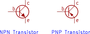
The arrow indicates the direction of conventional current through the emitter under the transistor’s normal forward-active operating conditions. It is a useful visual clue when identifying transistor types in circuit diagrams.
NPN Transistor Terminals: Emitter, Base and Collector
An NPN transistor has three terminals, each with a different function. Understanding these terminals is essential before connecting a transistor to a circuit.
| Terminal | Symbol | Function |
|---|---|---|
| Emitter | E or e | Emits charge carriers into the transistor’s base region during normal operation. |
| Base | B or b | Controls the transistor’s operation through a relatively small current. |
| Collector | C or c | Collects charge carriers and carries the controlled current through the transistor. |
In a typical NPN switching circuit, the emitter is connected to ground, the collector is connected to the load, and the other side of the load connects to the positive supply. A control signal is applied to the base through a suitable resistor.
When sufficient base current flows, the transistor can turn on and allow current to flow through the load. When the base current is removed, the transistor turns off, provided there is no other path driving the base.
The exact connections depend on the circuit design. For example, an NPN transistor can also be used in amplifier configurations in which the emitter is not connected directly to ground.

How Does an NPN Transistor Work?
An NPN transistor works by using a small base current to control the current flowing between its collector and emitter. Its behavior depends on the voltage between its terminals and the amount of current available from the surrounding circuit.
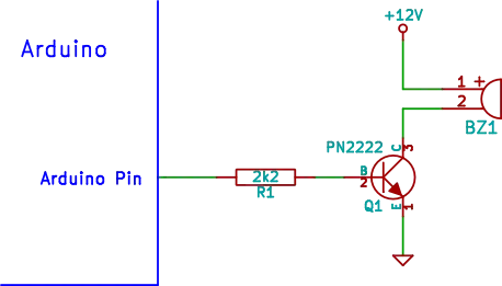
Consider a simple NPN transistor switch with a load connected between the positive supply and the collector, and the emitter connected to ground. For example, the following Arduino buzzer circuit that allows a 5V Arduino to switch a 12V buzzer.
1. NPN Transistor in the Off State
When the base is not driven sufficiently positive relative to the emitter, the transistor is normally off. Only a small leakage current flows through the collector-emitter path.
The load therefore receives little or no current from the transistor, so it remains off in a typical switching application.
2. NPN Transistor in the On State
When the base is driven positive relative to the emitter, the base-emitter junction becomes forward biased. For many silicon transistors, this voltage is approximately 0.6 to 0.7 V at modest currents, although the actual value varies with current, temperature, and transistor type.
Base current then controls the collector current. When the transistor is driven sufficiently hard into saturation, it behaves approximately like a closed switch, with a small voltage remaining between the collector and emitter.
In a switching circuit, the base resistor limits the current entering the base. It is important to calculate this resistor rather than connecting the base directly to a voltage source.
3. NPN Transistor as an Amplifier
An NPN transistor can also operate in its forward-active region, where changes in base current produce corresponding changes in collector current.
A small change in the input signal can therefore produce a larger change in the output signal. With suitable biasing and circuit components, this behavior can be used to amplify audio signals, sensor signals, and other analog signals.
Amplifier operation differs from switching operation. An amplifier normally needs an appropriate bias point so that the transistor does not remain fully off or become saturated throughout the signal cycle.
NPN Transistor Operating Modes
The operating mode of an NPN transistor determines how it behaves in a circuit, as illustrated in the following table.
| Operating Mode | Description | Typical Application |
|---|---|---|
| Cutoff | The transistor is off, apart from leakage current. | Switching a load off |
| Forward-active | Collector current is controlled by the base drive and transistor characteristics. | Signal amplification |
| Saturation | The transistor is driven fully on as a switch. | Driving LEDs, relays, and other loads within its ratings |
| Reverse-active | The collector and emitter roles are effectively reversed in a less useful operating configuration. | Rarely used in ordinary circuits |
For beginner projects, cutoff and saturation are particularly important because they describe the two main states of a transistor used as a switch.
A transistor should not automatically be treated as an ideal switch. The voltage across it when on, the current through it, and the resulting power dissipation all need to be considered.
NPN Transistor Pinout
The pinout of an NPN transistor identifies the physical locations of its emitter, base, and collector terminals. This information is essential when placing the transistor into a breadboard or connecting it to a circuit.
Do not assume that all NPN transistors have the same pinout. Two transistors that look almost identical can have different terminal arrangements.
The pinout may also be shown from different viewing directions. A diagram viewed from the flat front of a plastic package can look different from one viewed from the bottom where the leads enter the package.
Before using an NPN transistor, check the manufacturer’s datasheet for the exact part number and package.
PN2222 and KSP2222 Transistor Pinout
The PN2222 and KSP2222 are NPN transistors commonly used for general-purpose switching and amplification. They belong to the 2N2222 family of transistor types, but their exact specifications and physical packages can vary by manufacturer and part designation.
PN2222 and KSP2222 transistor examples from manufacturers:
The following image shows the NPN transistor symbol alongside a TO-92 plastic transistor package, with the emitter (E), base (B), and collector (C) terminals marked.
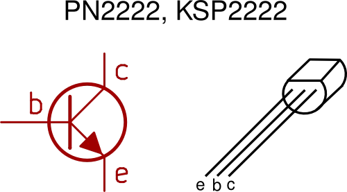
Use this image as a visual guide, but verify the terminal arrangement against the datasheet for the exact device you have. Pinouts can differ between manufacturers and related transistor versions.
2N2222, BC107, BC108 and BC109 Transistor Pinout
Some NPN transistors are supplied in a metal can package rather than a plastic package. Examples include traditional metal-can versions of the 2N2222 and the BC107, BC108, and BC109 transistor families. This type of package is a TO-18 metal case package.
These packages have a different physical appearance from the TO-92 plastic package. Their leads and package markings must be interpreted using the correct pinout diagram.
The following image shows the NPN transistor symbol on the left and the metal-can transistor package on the right. The package tag provides a reference point for identifying the terminals.
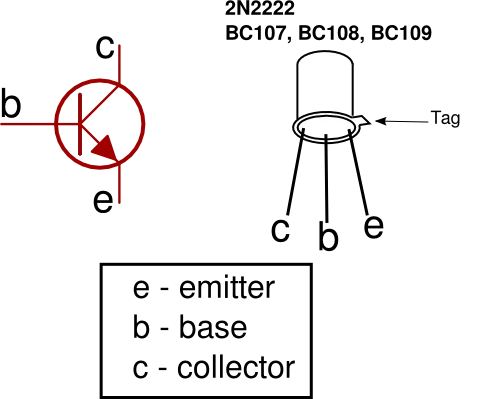
Important: Do not assume that the pinout shown for one metal-can transistor applies to every device in this group. The package style, manufacturer, and specific part number can affect the terminal arrangement. Always check the relevant datasheet before making connections.
Common NPN Transistor Types
Several NPN transistors are widely used in educational projects, hobby electronics, and general-purpose circuits. The best choice depends on the required collector current, voltage rating, switching speed, gain, and package.
| Transistor | General Description | Common Uses |
|---|---|---|
| 2N3904 | General-purpose small-signal NPN transistor | Signal amplification, low-current switching, and sensor circuits |
| 2N2222 | General-purpose NPN transistor family used in switching and amplification | Switching loads and driving small circuits within its ratings |
| BC547 | General-purpose small-signal NPN transistor | Amplifiers, sensor interfaces, and low-current switching |
| PN2222 | NPN transistor related to the 2N2222 family | General-purpose switching and amplification |
| KSP2222 | NPN transistor in the 2222 family | General-purpose switching and amplification |
| BC107 | General-purpose NPN transistor, available in metal-can versions | Small-signal amplification and switching |
| BC108 | General-purpose NPN transistor, available in metal-can versions | Small-signal amplification and switching |
| BC109 | General-purpose NPN transistor, available in metal-can versions | Low-level signal amplification and related applications |
These descriptions are general rather than a substitute for a datasheet. Maximum current, voltage ratings, gain, power dissipation, and package details can differ between devices and manufacturers.
The 2N3904 NPN Transistor
The 2N3904 is a popular small-signal NPN transistor used in many beginner electronics circuits. It is suitable for tasks such as switching low-current loads and amplifying relatively small signals.
It is often used in projects involving LEDs, simple oscillators, sensor circuits, and signal-conditioning stages.
When using this transistor, check the 2N3904 datasheet for its maximum collector current, voltage limits, power dissipation, and terminal arrangement. Do not assume its pinout is identical to that of the BC547 or another transistor in a similar package.
The 2N2222 NPN Transistor
The 2N2222 is another common NPN transistor used in general-purpose electronics. It is often chosen for switching applications because some versions can handle more collector current than many small-signal transistors.
However, the name 2N2222 is associated with devices supplied in different packages and related variants. The traditional metal-can 2N2222A and plastic versions such as the PN2222A should not be assumed to have identical pinouts or specifications.
For any project that uses a 2N2222, identify the complete part number and consult the manufacturer’s datasheet.
The BC547 NPN Transistor
The BC547 is a widely used small-signal NPN transistor that appears in educational electronics projects and general-purpose circuits. See the BC547 product page for more information and its datasheet.
It can be used for low-current switching, sensor interfaces, and signal amplification when the circuit operates within its ratings.
The BC547 is frequently supplied in a small plastic package, but the exact lead arrangement should still be confirmed using the datasheet. This is especially important when replacing it with a 2N3904, 2N2222, or another apparently similar transistor.
NPN v PNP Transistors: What Is the Difference?
NPN and PNP transistors are both types of bipolar junction transistors. They perform similar functions, but their semiconductor structures, normal current directions, and typical circuit connections differ.
The easiest way to distinguish them in a circuit diagram is to look at the emitter arrow.
| Feature | NPN Transistor | PNP Transistor |
|---|---|---|
| Semiconductor structure | N-type, P-type, N-type | P-type, N-type, P-type |
| Symbol arrow | Points outward from the emitter | Points inward toward the base |
| Typical base voltage for turning on | Positive relative to the emitter | Negative relative to the emitter |
| Conventional collector current in normal active operation | From collector to emitter | From emitter to collector |
| Common low-side switching arrangement | Load connected between positive supply and collector | Less common in a basic low-side arrangement |
| Common high-side switching arrangement | Requires suitable drive circuitry in many cases | Often used with the emitter toward the positive supply |
The differences between NPN and PNP transistors are important when choosing a component for a circuit. An NPN transistor is often convenient for low-side switching because its emitter can be connected to ground and its base driven positive relative to the emitter.
A PNP transistor is often used for high-side switching, where the transistor controls the connection between a positive supply and the load. The required control signal is different from that of a typical NPN low-side switch.
How to Choose an NPN Transistor
When selecting an NPN transistor for a circuit, consider more than the part number or physical appearance.
Check the following specifications in the manufacturer’s datasheet:
- Maximum collector-emitter voltage: The maximum voltage the transistor can withstand between the collector and emitter under specified conditions.
- Maximum collector current: The current limit for the device under the datasheet’s specified conditions.
- Power dissipation: The amount of power the transistor can safely dissipate, taking package and temperature limitations into account.
- Current gain: The relationship between collector current and base current under specified operating conditions.
- Switching characteristics: Important when the transistor is used to switch rapidly.
- Pinout: The physical positions of the emitter, base, and collector.
- Package type: Determines the physical size, lead arrangement, and thermal characteristics.
For a beginner project, a 2N3904 or BC547 may be suitable for small-signal switching and amplification. A 2N2222-family transistor may be more appropriate for some switching tasks requiring greater current capability.
The actual requirements of the circuit determine which component is appropriate. Do not choose a transistor solely because its name appears similar to the device specified in a project.
Using an NPN Transistor as a Switch
One of the most useful applications of an NPN transistor is controlling a load with a low-power signal.
In a typical low-side switching circuit, the emitter connects to ground, the collector connects to the load, and the other side of the load connects to the positive supply. The base receives a control signal through a resistor.
When the control signal drives the transistor into saturation, current flows through the load. When the control signal is removed, the transistor turns off.
A few practical rules will help you use this arrangement safely:
- Connect the emitter, collector, and base according to the transistor’s verified pinout.
- Use a base resistor to limit base current.
- Check that the transistor’s voltage, current, and power ratings are sufficient for the load.
- Connect the control circuit and load supply grounds together when required by the circuit design.
- If the load is inductive, such as a relay coil or motor, provide suitable protection against voltage spikes. A flyback diode is commonly used across a DC relay coil.
- Do not drive a load directly from a transistor if the required current or power exceeds the transistor’s ratings.
An NPN transistor is useful for controlling a load, but it is not always the right component for every switching job. High-current loads may require a power transistor or a MOSFET, along with suitable protection and thermal design.
Using an NPN Transistor for Signal Amplification
An NPN transistor can amplify a signal when it is biased in the forward-active region. In this mode, a small change in base current controls a change in collector current.
A common amplifier arrangement is the common-emitter circuit. The input signal is applied to the base, the output is taken from the collector, and the emitter is shared by the input and output circuits.
A properly designed common-emitter amplifier can provide voltage gain, but its performance depends on several factors:
- The transistor’s operating point.
- The values of the biasing and collector resistors.
- The load connected to the output.
- The input signal’s amplitude and frequency.
- Coupling and bypass capacitors, where used.
The transistor must be biased correctly to amplify a signal without unwanted clipping or distortion. Simply connecting an NPN transistor between a signal source and a power supply does not automatically create a useful amplifier.
Tips for NPN Transistors
Use these practical tips when building or troubleshooting circuits with an NPN transistor.
- Check the pinout first. Never assume that the three leads follow the same order on every transistor.
- Identify the viewing direction. Confirm whether a pinout diagram shows the transistor from the front, bottom, or another viewing angle.
- Use the correct part number. The 2N2222, PN2222A, and related devices may have different packages and specifications.
- Always limit base current. Use a suitably calculated base resistor when driving the transistor from a logic output or other voltage source.
- Check the load current. A transistor that works for an LED may not be suitable for a motor or relay.
- Consider power dissipation. Calculate the approximate transistor power as the voltage across it multiplied by the current through it. Check the datasheet’s thermal limits.
- Use a flyback diode for suitable inductive loads. A diode across a DC relay coil or similar inductive load can help protect the transistor from voltage spikes.
- Avoid confusing current gain with a guaranteed switching capability. The current gain listed in a datasheet varies with operating conditions. Design the base drive to ensure the transistor switches reliably.
- Use a datasheet from the actual manufacturer. This is especially important for devices obtained from different suppliers or sold under related part numbers.
- Test connections before applying power. A quick inspection can prevent damage caused by reversed leads or an incorrectly wired breadboard.
These checks are often enough to prevent common beginner mistakes when using an NPN transistor in practical electronics projects.
Did You Know?
The NPN transistor is part of a technology that helped transform electronics from bulky circuits based on vacuum tubes into compact, reliable electronic systems.
Here are some interesting facts about NPN transistors.
- Transistors can act as both switches and amplifiers. The same basic component can perform digital switching or analog signal amplification, depending on how it is biased and used.
- The base is very thin. In a typical BJT, the base region is designed so that most charge carriers injected by the emitter can pass through the base and reach the collector.
- A transistor does not need to be fully on or off. In amplifier circuits, the transistor normally operates between these two switching states, in its forward-active region.
- Transistors are not all interchangeable. Two NPN transistors can have similar appearances while differing in maximum current, voltage ratings, gain, switching behavior, and pinout.
- The transistor family includes many specialized devices. Some NPN transistors are optimized for low-noise amplification, others for high-frequency operation, and others for switching or power handling.
The basic NPN transistor remains an important building block in electronics, even though many modern circuits use integrated circuits and MOSFETs for tasks that once relied on individual bipolar transistors.
Frequently Asked Questions
What does NPN stand for in a transistor?
NPN refers to the transistor’s three semiconductor regions: N-type, P-type, and N-type. The central P-type region forms the base, while the two outer N-type regions form the emitter and collector.
How can I identify an NPN transistor symbol?
Look for the arrow on the emitter. In an NPN transistor symbol, the arrow points outward, away from the base. In a PNP transistor symbol, the arrow points inward toward the base.
What is the difference between a 2N3904, 2N2222, and BC547?
The 2N3904, 2N2222, and BC547 are all NPN transistor types, but they have different electrical specifications and may use different package and pinout arrangements. Their suitability depends on the required current, voltage, gain, switching performance, and other circuit requirements. Check the datasheet before substituting one for another.
How do I find the emitter, base, and collector pins?
Find the complete transistor part number and consult its manufacturer’s datasheet. The pinout diagram should identify the emitter, base, and collector and indicate the viewing direction. Do not rely on the physical shape alone.
Can I connect an NPN transistor directly to a microcontroller pin?
The base usually requires a resistor to limit current. The design must also keep the microcontroller pin’s output current within its specified limit and provide sufficient base drive for the transistor to switch the load reliably. For larger loads, a suitable driver circuit may be necessary.
Why is my NPN transistor not switching on?
Possible causes include an incorrect pinout, insufficient base current, incorrect polarity, a missing common ground, an unsuitable transistor, or a load current that exceeds the transistor’s capability. Check the circuit connections and measure the relevant voltages with a multimeter.
Does an NPN transistor need a resistor on its base?
In a typical circuit where the base is driven from a voltage source, a base resistor is needed to limit current. The required resistance depends on the supply or control voltage, the base-emitter voltage, the desired base current, and the characteristics of the driving circuit.
Some specialized circuits use other methods of controlling base current, but connecting a BJT base directly to a voltage source without considering current is generally unsafe.
Can I replace a PNP transistor with an NPN transistor?
Not usually as a direct replacement. NPN and PNP transistors have different current directions and control-voltage requirements. Replacing one with the other may require changes to the circuit connections and control logic.
Can an NPN transistor amplify an audio signal?
Yes. An NPN transistor can amplify audio signals when configured and biased appropriately, for example in a common-emitter amplifier. The transistor’s gain, noise characteristics, operating point, and surrounding components determine the amplifier’s performance.
Conclusion
An NPN transistor is a versatile component that can be used to switch electrical loads and amplify signals. Its three terminals, emitter, base, and collector, each have a specific function, and the outward-pointing emitter arrow distinguishes its symbol from that of a PNP transistor.
Understanding the operating modes of an NPN transistor, checking its pinout, and selecting a component with suitable electrical ratings are essential skills for building reliable circuits. Common types such as the 2N3904, 2N2222, and BC547 are useful starting points for learning about transistor switching and amplification.
Before using an NPN transistor in a project, always confirm its exact part number and consult the manufacturer’s datasheet. This simple habit helps prevent incorrect connections and makes it easier to build, test, and troubleshoot electronics circuits successfully.
Related articles:
- PNP Transistor: The Ultimate Guide to Symbols and Uses
- Transistor History: A Breakthrough That Shaped Tech
- What Is a Transistor? The Most Important Component
- Transistors Explained: Everything You Need to Know
- The Only Transistor Test You Need (Simple Multimeter Method)