
What is a multimeter, and why is it one of the most useful tools for anyone learning electronics? A multimeter is an electrical measuring instrument that combines several measurement functions in one device. It can measure quantities such as voltage, current, and resistance, and many models can also test continuity, diodes, and other electrical components. Whether you are building your first electronic circuit, troubleshooting a faulty device, or checking a battery, a multimeter helps you understand what is happening in an electrical circuit.
What Is a Multimeter?
A multimeter is an instrument used to measure different electrical quantities. Instead of needing a separate instrument for every measurement, you can use one multimeter to perform several common electrical tests.
For example, you can use a multimeter to check whether a battery produces the expected voltage, measure the resistance of a resistor, determine whether a wire is electrically connected from one end to the other, or measure the current flowing through a circuit.
Most beginners start with a digital multimeter because it displays measurements as numbers on a screen and is generally straightforward to use. The following image shows examples of various multimeters with their dials set to the diode test setting.

A typical multimeter has:
- A display that shows the measured value.
- A rotary selector or buttons for choosing measurement functions.
- Two test probes, usually one red and one black.
- Input sockets for connecting the test probes.
- Internal electronic circuits that process the measured signal.
The exact functions vary between models. Basic meters may measure only voltage, current, and resistance, while more advanced models may include capacitance, frequency, temperature, and other measurements.
A multimeter is especially valuable in electronics because it allows you to check actual electrical values rather than relying on assumptions about how a circuit should behave.
What Is a Multimeter Used For?
A multimeter is used to measure electrical quantities, check components, and help diagnose problems in electrical and electronic circuits. It is useful for beginners, hobbyists, technicians, and experienced electronics engineers.
Common applications include:
- Testing batteries: Measure the voltage of a battery to see whether it is producing an expected voltage.
- Checking power supplies: Measure the output voltage of a DC power supply or adapter.
- Measuring circuit voltage: Check the voltage across a resistor, LED, or other circuit component.
- Measuring current: Determine how much electric current flows through a circuit.
- Checking resistance: Measure the resistance of resistors and other suitable components.
- Testing continuity: Check whether a wire, track, switch, or connection provides an electrical path using a continuity test.
- Testing diodes: Use the diode-test function to check a diode’s forward voltage and basic operation.
- Testing transistors: Some multimeters have a built-in transistor tester, but a transistor test can also be done using the diode test function of a multimeter.
- Testing capacitors: Use a meter with a capacitance function to measure capacitance.
- Troubleshooting circuits: Find problems such as broken connections, incorrect supply voltages, and faulty components.
For example, suppose you build an LED circuit that does not work. You could use a multimeter to check the battery voltage, measure the voltage across the LED, test the resistor, and check for broken connections.
The meter does not automatically identify the faulty component, but its readings help you narrow down the possible causes.
What Can a Multimeter Measure?
What a multimeter can measure depends on the model. Most basic digital multimeters measure voltage, current, and resistance. Many also include additional functions for testing electrical connections and electronic components.
The following table summarizes common multimeter functions.
| Measurement or Test | What it tells you | Typical Application |
|---|---|---|
| DC voltage (V DC) | The electrical potential difference between two points | Measuring batteries, DC power supplies and DC circuits |
| AC voltage (V AC) | The alternating voltage between two points | Testing suitable AC sources |
| DC current (A DC) | The direct current flowing through a circuit | Measuring current in battery-powered projects |
| AC current (A AC) | Alternating current flowing through a circuit | Measuring AC current with a suitably equipped meter |
| Resistance (Ω) | Opposition to electric current, expressed in ohms | Checking resistors |
| Continuity | Whether a sufficiently low-resistance electrical path exists | Checking wires, switches, and circuit connections |
| Diode test | The forward voltage of a diode under the meter’s test conditions | Checking diode operation |
| Capacitance (F) | The capacitance of a component | Checking capacitors |
| Frequency (Hz) | The frequency of a periodic signal | Measuring oscillators and other signals |
| Temperature | Temperature measured using a compatible sensor | Checking component or ambient temperature |
Not every multimeter supports all these functions. Check the markings on the selector dial and consult the manufacturer’s manual before attempting a measurement.
It is also important to distinguish between a measurement and a diagnostic test. For example, measuring a battery’s voltage does not necessarily tell you how much usable capacity remains. A battery can show a reasonable voltage without being able to deliver its rated current for very long.
Understanding Voltage, Current, and Resistance
Voltage, current, and resistance are the three fundamental quantities measured by most multimeters. Understanding their differences makes it much easier to choose the correct function.
Voltage (V)
Voltage is the electrical potential difference between two points. It is measured in volts. A multimeter measures voltage by connecting its probes across the two points being tested. Voltage measurements are commonly used to check batteries and power supplies. Multimeters can usually test both alternating current (AC) voltages and direct current (DC) voltages.
Current (A)
Electric current is the rate at which electric charge flows through a circuit. It is measured in amperes, often called amps. Current flow is normally measured by placing the meter in series with the circuit so the current flows through the meter. The red lead or probe of the multimeter must typically be plugged into a different socket on the multimeter to measure current.
Resistance (Ω)
Resistance describes how strongly a material or component opposes electric current. It is measured in ohms, represented by the Greek letter omega (Ω). Resistance measurements are normally made with the circuit’s power switched off.
These quantities are related by Ohm’s law:
In this equation, is voltage in volts, is current in amperes, and is resistance in ohms.
For example, a 1,000-ohm resistor carrying 0.01 A of current has a voltage drop of 10 V. A multimeter can help you check these values in a real circuit.
What Is a Digital Multimeter?
A digital multimeter is a meter that displays measured values as numerical digits on an electronic screen. It is the most common type of multimeter used in modern electronics work.
Digital meters are popular because their readings are generally easy to interpret, and many models offer several measurement functions in a compact instrument. The following image shows the display of a digital multimeter as it is used to test the forward voltage of a diode. A value of 0.549V is measured, as can be seen on the screen. This particular make and model of multimeter is Amprobe 37XR-A.

Typical features include:
- A digital display, often with a backlight on more expensive models.
- Automatic or manual measurement ranges.
- Separate sockets for voltage, resistance, and current measurements.
- Continuity and diode-test functions.
- Overload indication when a measurement exceeds the selected range or the meter’s display capability.
- Additional functions, depending on the model.
Some digital multimeters use auto-ranging, which means the instrument automatically selects an appropriate measurement range. Others require you to choose the range manually on the selector dial.
For example, when measuring a 9V battery, an auto-ranging meter will generally select a suitable DC voltage range. On a manual-ranging meter, you may need to select a range above 9V.
Digital multimeters are not all equally accurate or equally safe. Their measurement accuracy, input impedance, maximum ratings, and protection features vary. A suitable meter should be chosen for the intended application.
What Is a DMM?
DMM stands for digital multimeter. The abbreviation is widely used in electronics documentation, product specifications, repair manuals, and technical discussions.
If you see a reference to a DMM in a circuit diagram or instruction manual, it usually means that a digital multimeter should be used for the specified measurement.
For example, an instruction might say to use a DMM to measure the voltage across a resistor. This means you should set a digital multimeter to the appropriate voltage function and connect its probes across the resistor.
The terms digital multimeter and DMM refer to the same type of instrument. The abbreviation does not indicate a particular brand, price range, or level of accuracy.
When choosing a DMM, consider its measurement ranges, accuracy, input protection, safety ratings, and the functions you need for your electronics projects.
What Is a Voltmeter?
A voltmeter is an instrument designed specifically to measure voltage, which is the electrical potential difference between two points in a circuit.
Traditional voltmeters may have moving needles, while modern voltmeters commonly use digital displays. A digital multimeter includes a voltmeter function, allowing it to measure voltage alongside other electrical quantities. The following image shows a digital multimeter set on the DC voltage scale, which effectively turns the multimeter into a voltmeter. Note that the dial on the multimeter is turned to the ‘V’ marking which has one solid line and one dashed line above it. This symbol marks DC voltage. The symbol below it is a ‘V’ with a ~ sine wave marking above it, representing AC voltage.
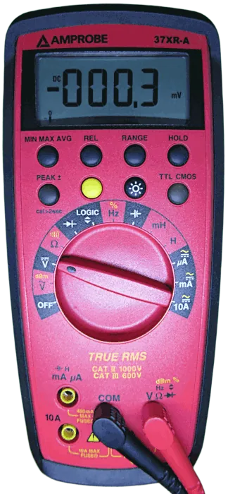
A voltmeter is connected in parallel with the component or part of the circuit being measured. This means the probes touch the two points between which you want to measure the voltage.
For example, to measure the voltage of a battery, connect the red probe to the positive terminal and the black probe to the negative terminal, using the meter’s DC voltage setting. A conventional positive reading indicates that the red probe is at a higher potential than the black probe.
A voltmeter is designed to have high input resistance so that it draws very little current from the circuit being measured. This helps reduce the effect of the instrument on the voltage reading.
The main difference is that a standalone voltmeter measures voltage, while a multimeter combines voltage measurement with other functions, such as current and resistance measurement.
What Is an Ohm Meter?
An ohm meter is an instrument used to measure electrical resistance in ohms (Ω). It can help determine whether a resistor has the expected resistance or whether a component or connection has an unexpectedly high resistance.
A multimeter includes an ohmmeter function, so you usually do not need a separate instrument for basic resistance measurements. The following image shows a multimeter set on the ohms or resistance setting. The multimeter is now ready to measure a resistance value by placing one probe onto one resistor terminal and the other probe onto the other resistor terminal. Note that the dial is set to the Ω symbol representing ohms, or resistance measurement. With the dial set to Ω, the multimeter effectively becomes an ohm meter.
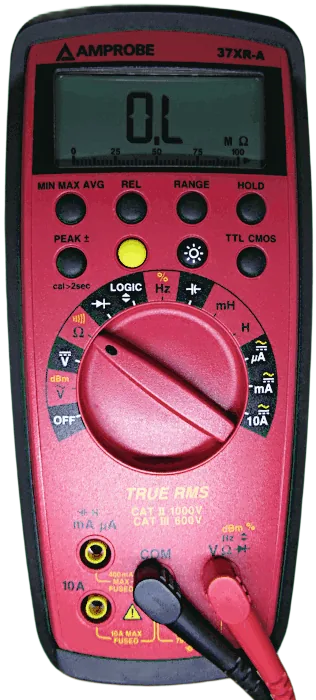
To measure resistance, the circuit should be switched off and isolated from any power source. Where necessary, discharge capacitors safely and disconnect one side of the component to reduce the influence of other circuit paths.
The meter applies a small internal test signal and uses the resulting electrical response to calculate resistance. This is why you must not measure resistance on an energized circuit: external voltage can produce incorrect readings and may damage the meter.
For example, if you want to check a resistor marked 1kΩ, select the resistance function and measure across the resistor. The result should be reasonably close to 1,000Ω, allowing for the resistor’s tolerance and measurement conditions.
An ohm meter function can also help identify open circuits, short circuits, and poor connections, although a resistance measurement alone does not prove that every type of component is working correctly.
What Is the Difference Between a Multimeter, Voltmeter, and Ohm Meter?
These instruments are closely related, but they do not have exactly the same purpose. Essentially a voltmeter is an instrument dedicated to measuring voltage, an ohm meter is an instrument dedicated to measuring resistance, and a multimeter is a multi-function tester. A multimeter can measure voltage, resistance and other electrical quantities, but only one at a time, depending on its dial setting. The following table compares the multimeter, voltmeter, ohm meter, and ammeter.
| Instrument | Main Purpose | Typical Use |
|---|---|---|
| Multimeter | Measures several electrical quantities | General electronics testing and troubleshooting |
| Voltmeter | Measures voltage | Checking the voltage between two points |
| Ohm meter | Measures resistance | Checking resistors and other unpowered components |
| Ammeter | Measures electric current | Determining current flowing through a circuit |
A multimeter combines the functions of a voltmeter, an ammeter, and an ohm meter in one instrument. Depending on its design, it may also offer continuity, diode, capacitance, and other testing functions.
For someone learning electronics, a basic digital multimeter is usually a practical first choice because it can perform many of the measurements needed for common circuits and projects.
How Does a Multimeter Work?
A multimeter works by sensing an electrical quantity and converting it into a reading that can be displayed or indicated to the user.
The internal measurement circuitry depends on the selected function. For voltage, the meter measures the potential difference between its input terminals. For current, it measures the electrical response produced as current flows through the appropriate input circuit. For resistance, it applies a small internal test signal and calculates resistance from the response.
The selector dial or buttons determine which measurement circuit is used.
On a typical digital multimeter, the basic process is:
- Select the measurement function, such as DC voltage or resistance.
- Connect the test probes to the correct input sockets.
- Place the probes at the correct points in the circuit or component.
- Read the displayed value and its units.
- Compare the result with the expected value to help identify possible problems.
The exact procedure depends on what you are measuring. Always check the meter’s instructions, particularly before measuring current or working with potentially hazardous voltages.
Why Does a Multimeter Show Different Units?
A multimeter may display volts (V), amps (A), ohms (Ω), millivolts (mV), milliamps (mA), or other units.
The unit tells you what the number represents. A reading of 5.0V is a voltage measurement, while a reading of 5.0Ω is a resistance measurement. Although the numbers are the same, they describe different electrical quantities.
Many meters also use prefixes to represent larger or smaller values:
| Prefix | Symbol | Meaning | Example |
|---|---|---|---|
| kilo | k | 1,000 times the base unit | 2 kΩ = 2,000 Ω |
| milli | m | One-thousandth of the base unit | 20 mA = 0.020 A |
| micro | µ | One-millionth of the base unit | 10 µF = 0.000010 F |
Pay attention to the unit and decimal point when reading the display. Confusing milliamps with amps, for example, can lead to a substantial error when interpreting a measurement.
What Types of Multimeters Are Available?
Multimeters come in several designs. The most suitable type depends on what you need to measure, where you will use it, and how much accuracy and protection you require.
Digital Multimeters
Digital multimeters display measurements as numbers. They are widely used for electronics projects, household troubleshooting, and electrical maintenance.
They are available in basic and advanced versions. A basic model may be sufficient for checking batteries, resistors, and low-voltage circuits, while an advanced model may offer greater accuracy, more measurement functions, and additional safety features.
Multimeter manufacturers often have different multimeter models for different target users. For example a multimeter aimed toward electrical use by electricians may be able to measure AC and DC voltage, resistance, continuity, diodes, and AC and DC current. On the other hand a multimeter aimed toward electronics work will usually have all the functions of the electrician’s multimeter plus be able to measure current in the milliamp and microamp ranges, and possible have a capacitor test setting, inductance test setting, frequency test setting, and logic level test setting.
Analog Multimeters
An analog multimeter displays readings using a moving needle over a graduated scale. The user must read the scale and select the appropriate range.
Analog meters can be useful for observing gradual changes in a measurement, but interpreting their scales can be more difficult for beginners. Many modern users prefer digital meters for everyday measurements.
Specialized Multimeters
Some meters are designed for particular applications. Examples include clamp meters that measure AC current by sensing the magnetic field around a conductor, and multimeters designed for industrial electrical work.
A clamp meter may measure current without requiring the conductor to be disconnected, although its capabilities depend on the model. Some clamp meters also include conventional multimeter functions.
For beginners working mainly with electronic components and low-voltage circuits, a standard digital multimeter is generally the most versatile starting point.
How to Choose a Multimeter for Beginners
You do not need an expensive multimeter to start learning electronics. A basic model with suitable measurement ranges and adequate protection can handle many beginner projects.
Before buying one, consider the following features.
- Voltage measurement: Look for AC and DC voltage functions with ranges appropriate for your projects.
- Resistance measurement: Ensure the meter can measure the resistance values you commonly use.
- Continuity testing: A continuity buzzer makes it easier to check wires, switches, and circuit connections.
- Diode testing: This is useful for checking common semiconductor components.
- Current measurement: Check the available current ranges, input sockets, and fuse ratings.
- Capacitance measurement: This can be helpful if you plan to test capacitors, but it is not essential for every beginner.
- Display readability: A clear display makes measurements easier to interpret.
- Input protection and safety ratings: Choose a meter suitable for the circuits and voltages you intend to test.
If you mainly build low-voltage electronic circuits, prioritize a suitable DC voltage range, resistance, continuity, and diode testing. If you plan to work with mains electricity, selecting an appropriately rated meter and understanding electrical safety become especially important.
A low price should not be the only consideration. The meter and probes must be suitable for the intended measurement, and the instrument should have appropriate protection against foreseeable measurement errors.
Some well known brands that offer high quality multimeters are from the following companies that manufacture not only multimeters but other test equipment too. These brands do not usually offer really low cost multimeters, but do offer good quality instruments.
The above list contains just a small sample of available multimeter and test instrument manufacturers. There are many more multimeter manufacturers offering many different models across different price ranges.
Tips on How to Use a Multimeter for Beginners
Understanding what a multimeter is is the first step. These practical tips will help you use one more effectively as you learn electronics.
1. Start with a low-voltage DC circuit. Practice measuring the voltage of a suitable battery before moving on to more complicated circuits. Beginners should stay away from high voltages which can be lethal.
2. Check the probe sockets before measuring. The black probe normally goes into the COM socket. The red probe goes into the voltage/resistance socket for those functions, or the designated current socket when measuring current.
3. Select the correct function. Use DC voltage for a typical battery, AC voltage for a suitable alternating-voltage source, and resistance mode for unpowered components.
4. Understand the connection method. Connect the meter in parallel for voltage measurements and in series for current measurements. Resistance is normally measured with the circuit unpowered.
5. Start with an appropriate range. If your meter has manual ranges and you do not know the expected voltage, start with a range higher than the anticipated value, provided it is within the instrument’s ratings. Reduce the range as needed for a clearer reading.
6. Never measure current by placing the probes directly across a battery. In current mode, the meter has a low-resistance current path. Connecting it directly across a voltage source can cause a short circuit, blow the meter’s fuse, damage the instrument, or create a safety hazard.
7. Do not measure resistance on a powered circuit. Switch off and isolate the power source first. Discharge capacitors safely according to the appropriate procedure.
8. Check the displayed units. Make sure you understand whether the reading is in volts, millivolts, amps, milliamps, ohms, or kilohms.
9. Learn the limitations of each test. A continuity beep does not prove that a connection can carry its intended operating current, and a battery voltage reading does not establish its full capacity.
10. Keep the meter and probes in good condition. Inspect the leads for damaged insulation and exposed conductors. Do not use damaged probes, and replace fuses only with the type and rating specified by the manufacturer.
For more detailed instructions, see our guides on testing a capacitor with a multimeter, performing a diode test, testing a transistor, and checking continuity.
Did You Know?
Multimeters have a long history in electrical testing. Earlier instruments often used moving-coil mechanisms and analog scales, while modern digital instruments use electronic measurement circuits and digital displays.
Here are some interesting facts about these instruments.
- One instrument can replace several others. A multimeter combines common measurement functions that would otherwise require separate voltmeters, ammeters, and ohm meters.
- The meter can influence the circuit. A measuring instrument is not always electrically invisible. Its input resistance, burden voltage, and other characteristics can affect a reading, particularly in sensitive circuits or current measurements.
- A continuity buzzer is not a complete component test. It tells you that the resistance between the probes is below the meter’s continuity threshold. It does not prove that a wire, switch, or connection will behave correctly under every operating condition.
- The same component can give different readings in a circuit and out of it. Other components connected in parallel or through alternative circuit paths can affect resistance measurements. This is why isolating a component may be necessary for an accurate result.
- Some meters can measure more than the basics. Depending on the model, additional functions may include capacitance, frequency, duty cycle, temperature, or transistor gain. The presence of a function does not mean that the meter can fully diagnose the component.
These details illustrate why a multimeter is such a useful troubleshooting tool, but also why it is important to understand what each reading actually means.
Frequently Asked Questions
What is a multimeter in simple terms?
A multimeter is an electrical testing tool that measures quantities such as voltage, current, and resistance. It can also perform other tests, depending on the model. It helps you check batteries, electronic components, wires, and electrical circuits.
What is a multimeter used for in electronics?
A multimeter is used to measure electrical values and troubleshoot circuits. Common tasks include checking battery voltage, measuring resistor values, testing continuity, checking diode operation, and investigating why an electronic circuit is not working as expected.
What is a digital multimeter, and is it better than an analog meter?
A digital multimeter displays measurements as numbers, while an analog meter uses a moving needle. Digital meters are generally easier for beginners to read and are widely used in modern electronics. However, the best choice depends on the application, required accuracy, and instrument specifications.
What is a DMM?
A DMM is a digital multimeter. It is an electronic measuring instrument that typically measures voltage, current, and resistance, with additional functions available on many models.
What is a voltmeter, and how is it different from a multimeter?
A voltmeter measures voltage between two points. A multimeter includes a voltmeter function but can also measure other quantities, such as current and resistance. A voltmeter is connected in parallel with the part of the circuit being measured.
What is an ohm meter used for?
An ohm meter measures electrical resistance in ohms. It can be used to check resistors, investigate poor connections, and identify open or short circuits. Resistance measurements should normally be made with the circuit switched off and isolated from its power source.
Can a multimeter test whether a battery is good?
A multimeter can measure a battery’s terminal voltage and help identify a discharged or faulty battery. However, voltage alone does not establish the battery’s remaining capacity or ability to deliver current under load. A more complete assessment may require an appropriate load test or battery tester.
Can a multimeter test every electronic component?
No. A multimeter can perform useful basic tests on many components, including resistors, diodes, and some capacitors and transistors. However, some faults only appear under operating conditions or require specialized test equipment. A component passing a basic multimeter test is not necessarily fully functional.
Is it safe to use a multimeter on a wall outlet?
Measuring mains voltage can expose you to potentially lethal electric shock. Only use a suitably rated meter and probes, follow the manufacturer’s safety instructions, and perform the measurement if you have the necessary training. Beginners who are unfamiliar with live electrical testing should seek help from a qualified electrician.
Conclusion: What Is a Multimeter and Why Do You Need One?
A multimeter is one of the most useful tools for learning electronics because it combines several electrical measurement functions in a single instrument. Understanding what a multimeter is, what it can measure, and how its different functions work will help you build circuits, test components, and troubleshoot electrical problems more confidently.
For beginners, a digital multimeter is a practical starting point. Learn to measure voltage, current, and resistance first, then progress to continuity testing and checking electronic components. Always select the correct function, use the appropriate probe connections, and follow safe measurement procedures.
If you are ready to get started, read our complete guide on how to use a multimeter, where you can learn the basic procedures for making measurements and find links to more detailed tutorials for testing batteries, capacitors, diodes, transistors, and circuit connections.